Thermal-Bridge-Free Smart Façades That Achieve ASHRAE 90.1 Compliance
Beyond CI Alone
.webp?t=1763648915)
Integrated structural insulated sheathing may be the future of streamlined, energy-efficient design.
Buildings account for about 40 percent of overall energy use – much of it fulfilling the basic tasks of keeping occupants cool in the summer and warm in the winter. To reduce energy consumption and make buildings more efficient, model building energy codes, such as the International Energy Conservation Code (IECC) and ASHRAE 90.1, consistently evolve to increase energy-saving standards across all climate zones. For many years now, exterior continuous insulation (CI) has been a primary means of achieving this efficiency by limiting the thermal shorts or conductive bridges that occur through a wall. But recent studies have shown that CI alone may not be enough for a building to achieve its designed level of energy efficiency. It’s time to look beyond CI alone and consider a holistic approach to façade design.
What’s the Big Deal About Thermal Bridging?
Thermal bridging happens when one part of a building component has higher thermal conductivity than the surrounding materials, causing a path of least resistance for heat flow. Most often, thermal bridges are caused by structural elements transferring loads from the building envelope to the greater building structure. They are weak spots in the building envelope that can significantly reduce the effectiveness of insulation and an assembly’s designed thermal efficiency. Thermal bridges lead to buildings that don’t heat or cool efficiently, have higher utility bills and an increased carbon footprint. Thermal bridges can also cause condensation when moisture in humid air within the building meets cold surfaces. And that can create the ideal environment for mold and rot, threatening the building’s indoor air quality and even structural integrity.
The Challenge: Energy-Efficient Exterior Walls That Perform as Designed
Continuous insulation is defined in the 2024 IECC as an insulation material that is continuous across all structural members without thermal bridges other than fasteners and service openings. To meet the code, design professionals must specify materials with a high insulating value per inch, or R-value. R-value is a material’s thermal efficiency, or ability to resist thermal transfer, as determined in laboratory conditions using the material only.
Simply adding high-R-value insulation to the exterior wall assembly does not guarantee an energy-efficient building. In a traditional assembly, cladding attachment sub-framing, furring, clips, fasteners and other conductive components can penetrate the thermal control layer, short-circuiting the insulation’s ability to block heat transfer. Once placed in a cavity between wood or metal studs, a material’s R-value can often be reduced by as much as 50 percent1. This measurement of the assembly’s R-value is called the effective R-value because it includes the thermal resistance of all insulation (both CI and cavity insulation) in the wall assembly and accounts for the thermal bridges caused by stud and framing members.
To truly determine if a wall assembly can achieve designed R-value in the field, consultants and design professionals need a more reliable way to measure thermal efficiency and adjust their designs accordingly.
Clear Field U-Factor Analysis: A Better Measure
Clear Field U-Factor Analysis is an important advancement in wall assembly modeling software that has enabled consultants and design professionals to look at a given wall assembly and determine much more accurately just how efficient it will be when installed on a building.
U-Factor is the measure of thermal conductance for an entire wall assembly. Modeling software is used to account for the R-value of ALL materials in the assembly, the assembly’s effective R-value and the collective effects thermal bridging components have on the assembly’s thermal conductivity.
When Clear Field U-Factor modeling is used to measure thermal conductivity, many traditional commercial wall assemblies are found to have a lower effective R-value than originally designed. This modeling shows the wall assembly design matters even more than simply using a high-R-value insulation material.
Decoupling Cladding Attachment From Structural Framing Cuts Thermal Bridging
A number of integrated panel systems on the market combine insulated sheathing with structural panels. The resulting composite system provides highly effective continuous insulation that can significantly reduce thermal bridging. While both the insulation and structural components vary in their efficacy, some have proven to eliminate highly conductive metal sub-girt assemblies, effectively “decoupling” the cladding attachment from the structural framing component of the assembly.
As one example illustrating the importance of design and understanding the intent of the code regarding continuous insulation, the IECC recognizes that composite systems outperform traditional assemblies to meet ASHRAE 90.1. Moreover, using a composite system with enough CI can help comply with new prescriptive codes and offers a path to compliance without using any cavity insulation. See Table C402.1.3, Opaque Building Thermal Envelope Insulation Component Minimum Requirements (R-Value Method), from chapter 4 of the 2024 Commercial Energy Efficiency Code for further details.
See Figure 2 below for examples of coupled and decoupled assemblies.
Case Study: Clear Field U-Factor Modeling of a Decoupled System
At DuPont, we commissioned third-party de-rating testing by Stantec (formerly Morrison Hershfield) using Clear Field U-Factor performance modeling to evaluate the performance of an exterior wall assembly that incorporates structural insulated sheathing, allowing direct cladding attachment. Sold under the brand name DuPont™ ArmorWall™ System, the decoupled system evaluated also provides fire, air and water resistance and high-performance continuous insulation in addition to structural sheathing.
Unique to this system is a magnesium oxide (MgO) sheathing fused to an ultra-low-global warming potential (GWP) continuous insulation layer, creating an exceptionally strong, durable structural panel that allows direct cladding attachment. This quality of the MgO sheathing dramatically reduces the thermal bridging through wall framing that is inevitable with conventional assemblies. Combined with its factory-applied air- and water-resistive barrier, DuPont’s system significantly reduces both conductive and convective heat transfer, resulting in a wall assembly that preserves maximum designed R-value. Moreover, the MgO-infused sheathing enables NFPA 285 approval and up to 2-hour UL fire-rated assemblies.
Components of the decoupled wood- and steel-framed assemblies Stantec evaluated are outlined here.
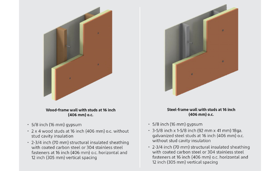
Figure 2. Components of Two Decoupled Wall Assemblies Evaluated. Image courtesy of DuPont
Clear Field U-Factor Results: DuPont’s Decoupled System
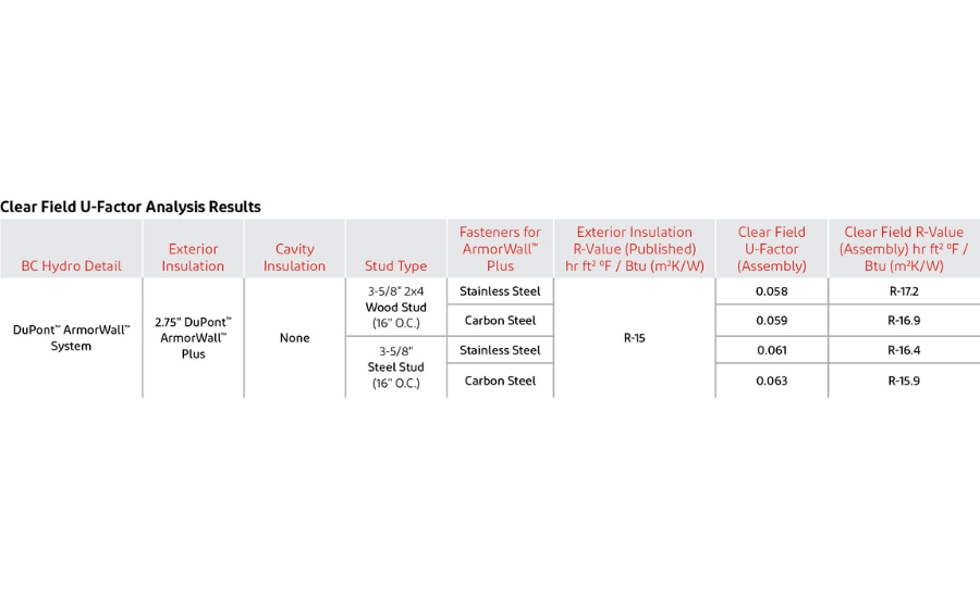
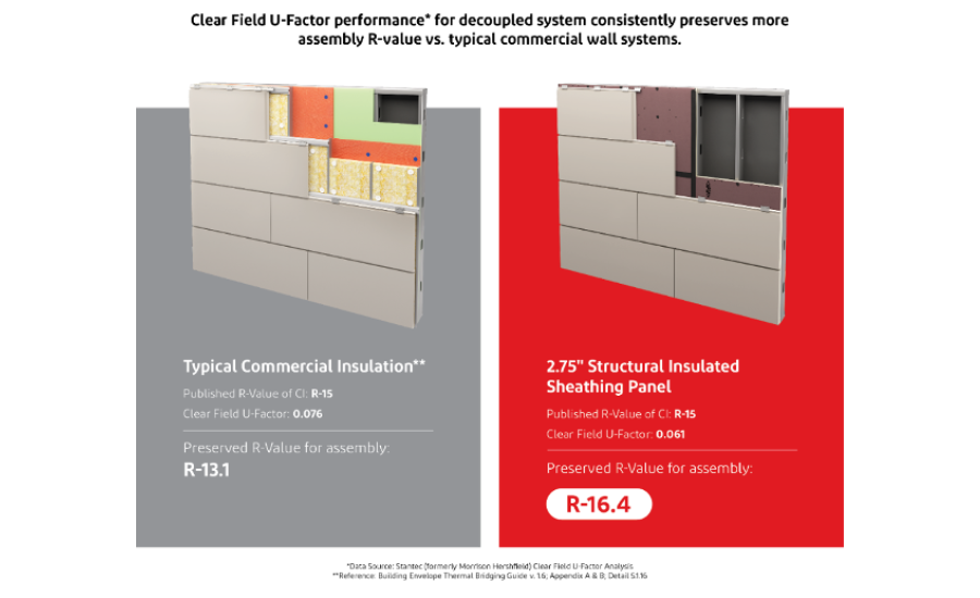
Stantec systematically compared various commercial wall system assemblies, with a specific focus on Clear Field U-Factor performance. The data shown in Table 1 and Figure 2 validate that assemblies incorporating the decoupled system demonstrate Clear Field U-Factors that preserve more of the designed R-value of the wall assembly – up to 93 percent. In contrast, comparable typical commercial wall assemblies demonstrated greater loss of designed R-value once the entire wall assembly U-Factor was assessed.
DuPont
*See Figure 2 for example of assembly details.
Figure 3. Comparison of Typical Assembly vs. DuPont’s Decoupled System. Image courtesy of DuPont.
Integrated Systems Can Reduce Thermal Bridging, Preserve More Designed R-Value and Meet or Exceed ASHRAE 90.1
Shifting the focus from building components to façade design and prioritizing U-Factor over R-value holds great promise for developing more cost-effective building practices and innovative solutions that maximize a wall assembly’s designed R-value. It also makes it easier than ever to meet and even exceed the strictest energy codes.
According to Stantec’s comparative analysis, certain decoupled assemblies:
- Exhibit superior performance in minimizing thermal transmittance
- Outperform many conventional assemblies by yielding a lower Clear Field U-Factor
- Can help enhance energy efficiency by minimizing heat loss when installed on commercial buildings
- Can help significantly reduce operational costs over the building’s lifespan
In addition, both conductive and convective transfer – the two primary thermal transmitting methods through the exterior wall assembly – can be reduced significantly when the integrated assembly includes an air- and water-resistive barrier component.
The bottom line: Integrating structural insulated sheathing into commercial building exterior wall assemblies can help designers, owners and other stakeholders meet stringent energy code standards, achieve higher thermal performance and deliver a streamlined solution. This novel multilayer façade design represents a giant step forward in the future of commercial construction.
References
[1] Source: ASHRAE 90.1-2022, Table A3.3.3.1.
Looking for a reprint of this article?
From high-res PDFs to custom plaques, order your copy today!
.webp?height=740&t=1767036885&width=auto "Header - BE 1170x658 (002).png")

.webp?height=740&t=1755781744&width=auto "KEE(2).png")
-Homepage.webp?height=200&t=1680015975&width=200 "BE_Podcast (03A)-Homepage.jpg")