Evaluating High Thermally Performing Hybrid Curtain Wall Systems
No Track Record? No Problem

Energy codes are constantly updating to establish requirements for more sustainable and energy-efficient building enclosures. These updates typically include higher thermal performance requirements for facade systems. It is becoming more and more challenging for curtain wall systems—even thermally broken curtain wall systems—to meet these increased thermal requirements. What should designers and owners who desire a curtain wall facade do? Do we need to abandon glass building facades in favor of the predominantly opaque clad buildings of the past? Fortunately, we think not.
This paper will present two options for meeting the high thermal requirements in the updated energy codes. In the first option, we will review optimization of available curtain wall systems, including modifications available to designers to improve thermal performance, including optimizing curtain wall geometry, configuration, and glass makeup.
What if, even with all these improvements, the available curtain wall systems still do not meet code-mandated thermal requirements? What if thermal improvements make these systems more costly and too expensive to construct? Manufacturers are actively developing higher performing thermal curtain wall systems to meet the design flexibility sought by professionals and to comply with increasingly stringent code requirements for lower U-factors. While on paper these systems seem enticing, these curtain wall systems are new to the market and do not have a track record of proven in-service performance.
In the second option, we will discuss how to evaluate these new high thermally performing curtain wall systems to demonstrate that the systems meet not just thermal requirements but all performance requirements, including air, water, and structural performance, until a proven track record of success can be established.
Climate change mitigation efforts in the AEC industry have driven code revisions to improve sustainability and resiliency in building construction, resulting in increasingly stringent energy code requirements for building enclosures, particularly for glazed curtain wall system, which have traditionally presented challenges in meeting thermal performance and occupant comfort goals. Massachusetts has set itself as one of the frontrunners for this effort with their updated Stretch Energy Code, focusing on design and construction of high thermally efficient building enclosures.
As part of this effort, the Massachusetts Stretch Code includes a new term, “glazed wall systems,” which applies to a system that includes both vision glazing and spandrel sections that are designed to separate exterior and interior environments. These glazed wall systems are required to achieve a maximum whole assembly U-factor of U-0.25, which is a low value relative to the fixed fenestration U-factor energy code requirements in other states. For example, the 2022 California Energy Code currently prescriptively requires a maximum U-factor for glazed wall systems of U-0.34 or U-0.36, depending on climate zone. Following the trend seen in Massachusetts within the last five years, we expect future code updates in colder climate zones to continue driving lower U-factors for glazed wall systems.
Owners, developers, and architects recognize the advantages of building facades that feature glazed wall systems. In design, off-the-shelf thermally broken curtain wall systems with either standard aluminum (Figure 1) or typically thermally broke frames that implement a combination of aluminum and thermal brake materials to improve thermal performance (Figure 2) are often used to establish basis of design systems within contract documents.
 All images courtesy of SGH.
These systems have long-established successful track records of ten to fifteen years or greater, demonstrated both in service and via laboratory testing, of compliance with the typical code and performance requirements, including the following:
- Structural Loads: Dead loads and live loads, including but not limited to wind, seismic, barrier (person or group of people leaning against the curtain wall), accidental loads (such as stepping loads on horizontal projections), façade access equipment impact loads, and snow, ice, and rain loads.
- Deflections: Wind and seismic inter-story drift, differential building structural movement (from dead load, superimposed dead load, façade dead load, live load slab edge deflection, etc.), deflections normal and parallel to the face of the curtain wall plane, deflection of cantilevered elements, and aluminum members spanning door openings.
- Thermal Movement: Thermal deflections and movements (expansion and contraction) resulting from maximum change in ambient and surface temperatures.
- Airtightness and Watertightness Performance: Maximum air leakage rates under static air differential pressure that do not evidence water penetration when tested to static and dynamic differential pressure.
- Solar, Thermal, and Condensation Performance: Solar heat gain coefficient (SHGC), visible light transmittance (VLT), thermal transmittance (U-factor), and condensation resistance.
Standard thermally broken curtain wall products often have U-factors that do not meet the new code driven U-factors for glazed wall assemblies (i.e., for Massachusetts in particular). However, these systems are desirable because they demonstrate compliance with the other performance requirements described above, can eliminate the need for additional performance testing during preconstruction (which can be costly and time consuming), and are readily available on the market, making them cost-competitive and ideal for projects that require shorter lead times. Options to modify these standard curtain wall systems to optimize thermal performance include the following:
- Maximize curtain wall geometry to improve thermal performance.
- Use larger panel sizes to reduce frame effect on curtain wall assembly U-factors. When evaluating the thermal transmittance of curtain wall systems, we start with the U-factor for the center of glass (the C.O.G. U-factor) and reduce it based on the frame-to-glazing ratio for the project specific panel sizes. The larger the glazing panel, the less impact from the frame components on the C.O.G. U-factor. Additionally, the thinner the frame, the less of an impact on the C.O.G. U-factor.
- Use a curtain wall configuration with a lower system U-factor.
- Utilize structural silicone glazed (SSG) systems, which offer slim sight lines and lower assembly U-factors than captured curtain wall systems with beauty caps and pressure bars that allow for more heat transfer through these components through the frames.
- Utilize curtain wall systems with thermal break materials incorporated within their mullion extrusions and profiles to help mitigate thermal bridging.
- Where structurally possible (such as within shadow box or opaque spandrel areas), introduce partial depth mullions to help limit heat transfer at these portions of the curtain wall frame.
- At spandrel areas, a mullion backwrap of insulation (insulation added to the back of the mullions) or added insulation to the back side of the spandrel areas can improve the thermal performance at the spandrel condition. This option must be carefully reviewed with thermal modeling to determine the location of the dewpoint within the spandrel assembly, as it may be pushed inward due to the added insulation. This system should be avoided in this instance as it is often challenging to detail the vapor retarder continuously as required to prevent warm, conditioned air from entering and potentially condensing within the spandrel.
- Adjust the glass makeup to produce lower C.O.G. U-factors to drive the curtain wall system U-factor down.
- Insulated Glass Units (IGU): Using triple glazing offers more insulative value due to the additional glass layers and air spaces introduced within the assembly.
- Warm Edge Spacers: Spacers made from low-conductivity materials, such as stainless steel/thermoplastic, hollow-tube type, filled with a low-nitrogen-absorption desiccant, result in better thermal performance than traditional aluminum spacers by minimizing heat transfer through the IGU perimeter.
- Multiple Low Emissivity (low-e) Coatings on Multiple Glass Surfaces: Use low-e coatings on the #2, or #2 and #4 surfaces for double glazing and the #2, #4, and #6 surfaces for triple glazed IGUs. Room side low-e coatings are hard coats pyrolytically fused to the glass similar to a frit coating, whereas coatings used within the air space of an IGU are soft coats and are easier to damage relative to the hard coats Pyrolytic coatings can be damaged with effort (similar to scratching glass with an abrasive like sandpaper) but tend to be much more durable than soft coat low-e. Note that using interior low-e coatings requires careful analysis, as there may be a risk of condensation on the interior surface of the glass depending on the project location and set interior conditions of relative humidity and temperature. Thermal analysis will need to be performed to understand this condensation risk before introducing room-side low-e coatings to the interior surface of the glazing. Owners and designers should review the visual transmittance and transparency of the glazing against project goals to confirm that multiple low-e coatings do not result in an undesirable appearance.
- Air, Argon, or Krypton: In the air space within the IGU, regular air can be used, or, if more insulative properties are desired, a combination of air and argon gas or krypton gas may be used. For example, using 10% air with 90% Krypton within the air space is the most insulative option. Additionally, vacuum insulated glass also significantly improves the C.O.G. U-factor.
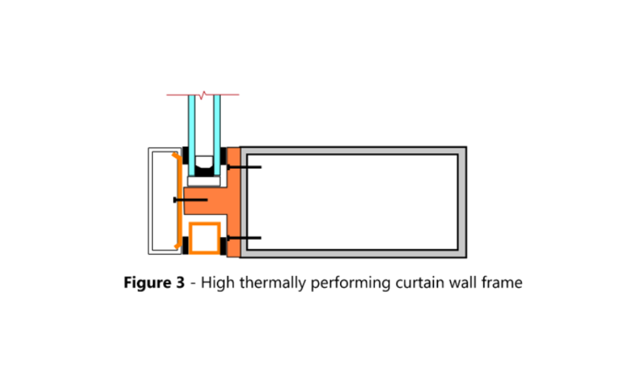
If, despite these improvements, the available curtain wall systems still do not meet code-mandated thermal requirements, or if thermal requirements are met but the system becomes too costly to build and/or is no longer constructible, then design teams turn to new high performing thermally resistive curtain wall systems with larger, more significant thermal breaks (Figure 3) to limit thermal bridging. Manufacturers are actively working to these curtain wall systems to meet the demand and versatility that design professionals seek in glass buildings while achieving code-driven lower system U-factors.
While these systems may seem enticing on paper, these curtain wall systems are new to the market and do not have a track record of proven in-service performance. We discuss below how to evaluate these newer hybrid-type systems until a proven track record of success can be established. To demonstrate compliance, the evaluation should focus on not just understanding the thermal performance but understanding all performance requirements, including air, water, and structural performance, etc.
- With a standard curtain wall system, the design team can rely on laboratory test reports and published performance data. With newer hybrid systems, the team should proceed with a delegated design approach, employing a curtain wall fabricator and installer with design and engineering services within the project’s jurisdiction.
- Performance mockup testing should be performed to demonstrate the product’s performance relative to the specified project requirements. Performance mockup testing should include the following tests, in the order described below:
- Preloading at 50% positive and negative peak design load, ASTM E330.
- Air infiltration/exfiltration at static air pressure differential, ASTM E283 and ASTM E1186.
- Water penetration resistance at static air pressure differential for one fifteen-minute cycle, ASTM E331.
- Water penetration resistance under dynamic pressure for one fifteen-minute cycle, AAMA 501.1 (note that the American Architectural Manufacturer’s Association (AAMA) has merged with Insulating Glass Manufacturers Alliance (IGMA) to form one organization, Fenestration and Glazing Industry Alliance (FGIA).
- Uniform load structural deflection performance at 100% the peak design load (positive and negative), ASTM E330.
- Air infiltration/exfiltration at static air pressure differential, ASTM E283 and ASTM E1186.
- Water penetration resistance at static air pressure differential for one fifteen-minute cycle, ASTM E331.
- Horizontal interstory movement performance for three full cycles at the greater of wind or seismic interstory drift, AAMA 501.4.
- Air infiltration/exfiltration at static air pressure differential, ASTM E283 and ASTM E1186.
- Water penetration resistance at static air pressure differential for one fifteen-minute cycle, ASTM E331.
- Vertical interstory movement performance for three full cycles at the design displacement, AAMA 501.7.
- Air infiltration/exfiltration at static air pressure differential, ASTM E283 and ASTM E1186.
- Water penetration resistance at static air pressure differential for one fifteen-minute cycle, ASTM E331.
- Thermal cycling and condensation resistance testing for three cycles per AAMA 501.5-05 Test Method for Thermal Cycling of Exterior Walls and Condensation Resistance.
- Air infiltration/exfiltration at static air pressure differential, ASTM E283 and ASTM E1186.
- Water penetration resistance at static air pressure differential for one fifteen-minute cycle, ASTM E331.
- Uniform ultimate structural deflection performance, no permanent deformation exceeding 0.1% of the span at 150% of the peak design load, ASTM E330.
The above battery of tests are typically performed on any curtain wall assembly and are applicable for testing the newer high performance and hybrid glazed wall assemblies as well. For the newer hybrid-type thermal system, additional testing should be performed to demonstrate that the hybrid components of the system can also perform to the expected structural and durability levels that systems with long track records of in-service performance already demonstrate. This additional testing should include the following:
- Test to demonstrate that the system can successfully retain both double and triple glazing, withstand the gravity load from the glazing, and distribute these loads back to the aluminum mullion.
- Perform sealant adhesion testing on the weather and structural seals on all materials, including the thermal break materials such as pultruded fiberglass or polyamide thermal break materials. Perform sealant adhesion testing of the sealant used to seal the end dams of the thermal break at the intersections and perimeter termination of the mullions. Perform sealant adhesion testing of the silicone sheet transition membrane seals to the thermal break materials.
- For captured systems or any conditions with fasteners through (or into) the thermal break material, perform pullout testing to confirm the pressure bar fastener engagement does not result in a loss of compression between the glass and the glazing gaskets. Perform this testing under both cold weather and hot weather extreme temperature conditions. The latter requirements for these tests are necessary to confirm that the thermal break materials have appropriate physical properties to perform under a wide range of temperature and loading conditions.
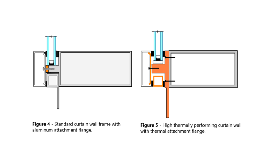
- For the condition where the curtain wall may be attached with a fiberglass or other composite-type flange (Figure 5, refer to Figure 4 for a standard curtain wall frame with aluminum attachment flange), test the flange for bending stress and strain-to-failure to determine if the flange can meet the anticipated wind and overload wind conditions. Document if cracking, elastic failure, or pullover of the fastener is observed during loading.
- Perform load testing to verify tensile and shear loading.
- Perform creep testing to evaluate the ability of the thermal break material and adhesive bonds between the thermal break material and aluminum mullion extrusion to support the glass. Apply a perpendicular load consistent with the weight of the glass to the tongue of the thermal break, hold for a 24- to 48-hour period and evaluate if there is a reduction in the load over time and if the stem deflects (i.e., the stem is creeping downward and thus causing a reduction in the applied load).
- Evaluate the creep of the fasteners. Set a torque for fastener penetration into the thermal break receiver, check at set increments such as 24 hours, 48 hours, 72 hours, weekly, etc., for a reduction in torque, which would indicate creep in the fastener. Check if the resulting torque on the fastener is still above the anticipated design load on the fastener. Historically, we have found reduction in torque in certain similar composite materials. Loss of torque means the fastener is not compressing the glazing gaskets against glass, which allows excess air and water into the glazing pocket and could potentially result in leakage to the interior of the building.
- Evaluate the glazed wall system for missile impact if the end use will be in a hurricane-prone region, ASTME1886. Perform this testing under both cold weather and hot weather extreme temperature conditions to confirm that the polymeric thermal break materials have appropriate physical properties to perform under a wide range of temperature and loading conditions.
In addition to the physical testing listed above, confirm thermal and condensation performance with thermal modeling as follows.
- Thermal transmittance (U-factor) should be determined using the project-specific curtain wall panel size, frame components, and glazing system according to NFRC 100 and AAMA 507. Include center-of-panel, frame, and edge effects and perform the evaluation for each curtain wall type and sizes, focusing on the smaller panel sizes as these U-factors will govern. Standard NFRC 100 panel sizes are not acceptable as these may be larger than the project’s module size and therefore provide lower U-factors that do not accurately reflect the actual thermal performance of the project-specific curtain wall.
- Typically, a condensation resistance factor is included in the project specifications. This value alone does not indicate if condensation will form on the interior surfaces of the curtain wall system in service. Rather, condensation resistance should be verified by performing computer thermal analysis in accordance with NFRC 500 using the latest version of THERM computer software to determine that (1) condensation does not occur on interior surfaces and that (2) internal condensation and drainage systems prevent uncontrolled condensation inboard of the vapor barrier plane. Calculations should be performed under the most onerous combination of project-specific environmental design conditions, interior construction, finishes, air temperature, and relative humidity conditions. Obtain the correct environmental design conditions from ASHRAE 90.1 for the project site.
The testing and analysis described above provide a set of checks to verify the performance of innovative curtain wall systems developed by curtain wall fabricators to meet the industry’s ever-changing need for high thermally performing systems. Results from structural calculations and thermal modeling should be verified by comparing the values against the results from the physical testing. Once fabricated and installed, quality control measures and field verification testing should be performed to verify that contractors can successfully install and integrate high-performance/hybrid thermal systems into adjacent building enclosures.
The information gathered during the evaluation process provides confidence for design and construction teams to proceed with using systems with limited track records. Utilizing these high performing curtain wall systems will help design and construction teams meet increasingly stringent energy performance requirements while still allowing designers to feature glazing systems within building facades. The standard performance requirements for curtain wall systems should not be compromised in favor of high thermal performance. The testing and evaluation process outlined above provides assurance that all the project requirements can be met.
Looking for a reprint of this article?
From high-res PDFs to custom plaques, order your copy today!
.webp?height=740&t=1767036885&width=auto "Header - BE 1170x658 (002).png")

.webp?height=740&t=1755781744&width=auto "KEE(2).png")