Critical Low-Slope Roofing Details

The most critical application points on low-slope roof systems are at flashings, penetrations and accessories. These critical junctures account for the majority of roof leaks. Problems at these points typically arise from improper application methods and the use of inappropriate or incompatible materials. Designers and specifiers should pay close attention to roofing details in these areas and make sure their instructions are followed by installing contractors in the field. In all cases, use the roof system manufacturer’s approved products and complete the roofing details in accordance with their requirements.
The following are basic guidelines for proper application of some of these critical roofing details.
Perimeter Gravel Stop
Perimeter gravel stops serve four primary functions on a roof system. They are:
1. To act as a barrier to hold aggregate in place.
2. To serve as an edge termination for the membrane.
3. To act as a rain shield.
4. To serve as top surface for securement of the fascia metal.
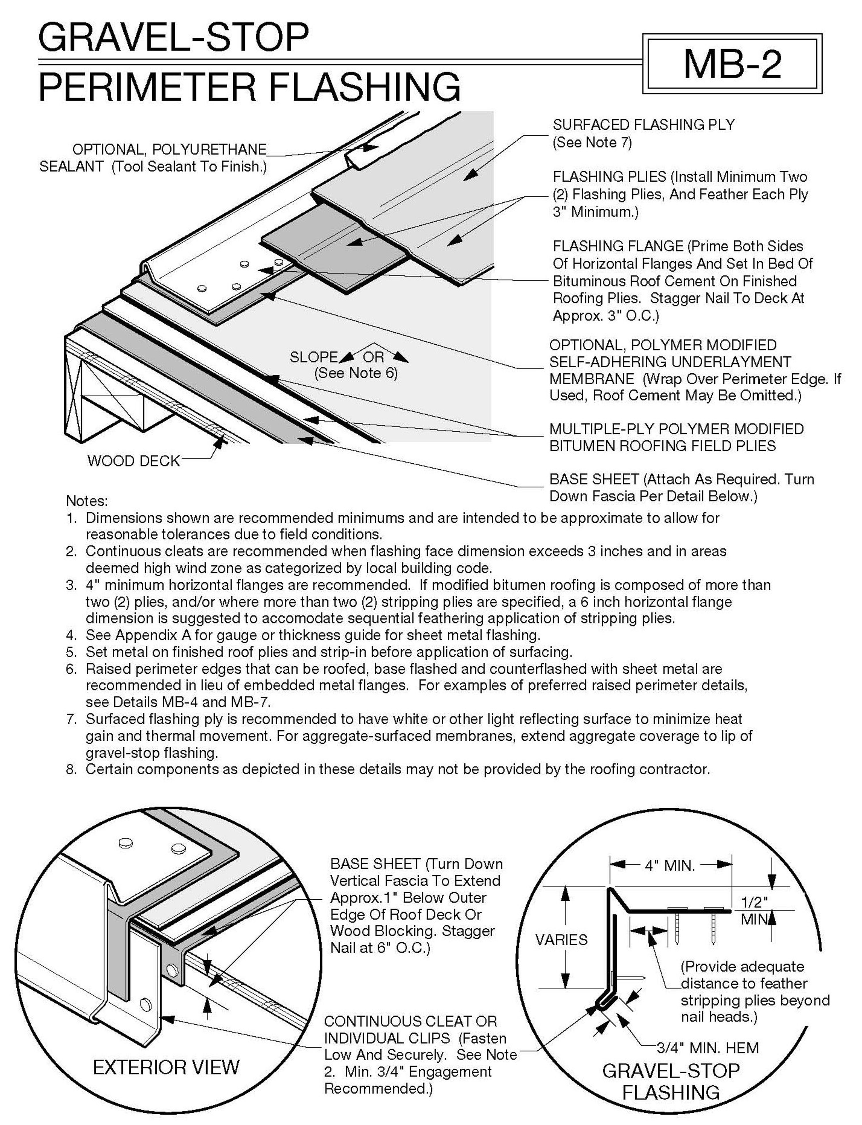
The gravel stop should be raised above the roof elevation with a sloped cant strip or wood nailer. (See Figure 1.) The materials used for gravel stops must be metal or premolded plastic. The material must be watertight and flexible enough to accommodate thermal and differential movement. The flange width should be a minimum of 4 inches and not greater than the width of the nailer. Metal thickness should be in compliance with Factory Mutual Loss Prevention Data Sheet 1-49.
After a two-by-four wood nailer is installed at the perimeter edge to receive flashing and new metal, install one ply of flashing membrane over the top of the nailer and down and out onto the roof. It should extend approximately 6 inches beyond the base of the wall in an even application of the approved adhesive.
Following the same procedure, install a second ply of flashing membrane. This ply shall extend from the maximum flashing height down and onto the roof, approximately 2 inches beyond the previously installed Ply.
Install a new perimeter edge fascia/gravel stop fabricated from similar metal material and color to match existing perimeter metal in width and fascia height. The gravel stop shall be secured with the appropriate fasteners every 8 inches on center.
Apply the approved butyl rubber sealant caulking at all metal coping joints. Caulking shall be completed in accordance with the manufacturer’s latest printed specifications. All flashing seams must be sealed with an application of roof adhesive, membrane and aluminum coating.
Roof-to-Wall Expansion Joint
In specific situations where the structural roof deck is not attached to the wall and an opening is provided, a roof-to-wall expansion joint is required. The installation of the roof-to-wall expansion joints allows for differential movement between the two construction components.
A curb must be installed at the perimeter edge of the structural decking to serve as a substrate for the flashing and expansion joint materials. The curb can be fabricated from treated wood blocking, concrete masonry units or a structural concrete pour.
The roof flashing material should be applied to the top of the face of the curb following the attachment procedures required by the membrane manufacturer. The material used for the roof-to-wall expansion joint must be in compliance with the membrane manufacturer’s requirements. Most manufacturers allow for the use of prefabricated expansion joints. The manufacturer of the prefabricated expansion joint should be consulted for specific material and application procedures. The expansion joint material is set at the top of the curb and out onto the wall. The beveled expansion joint is set over the opening between the deck and the wall.
A metal termination bar is then set over the roof-to-wall expansion joint at the top of the wall flashing and at the bottom of the curb flashing. The termination bar shall be secured to the substrates with the appropriate fasteners at a fastening rate of 12 inches on center. A bead of structural sealant should be set at the top of the termination bars.
High Concrete Parapet Flashing
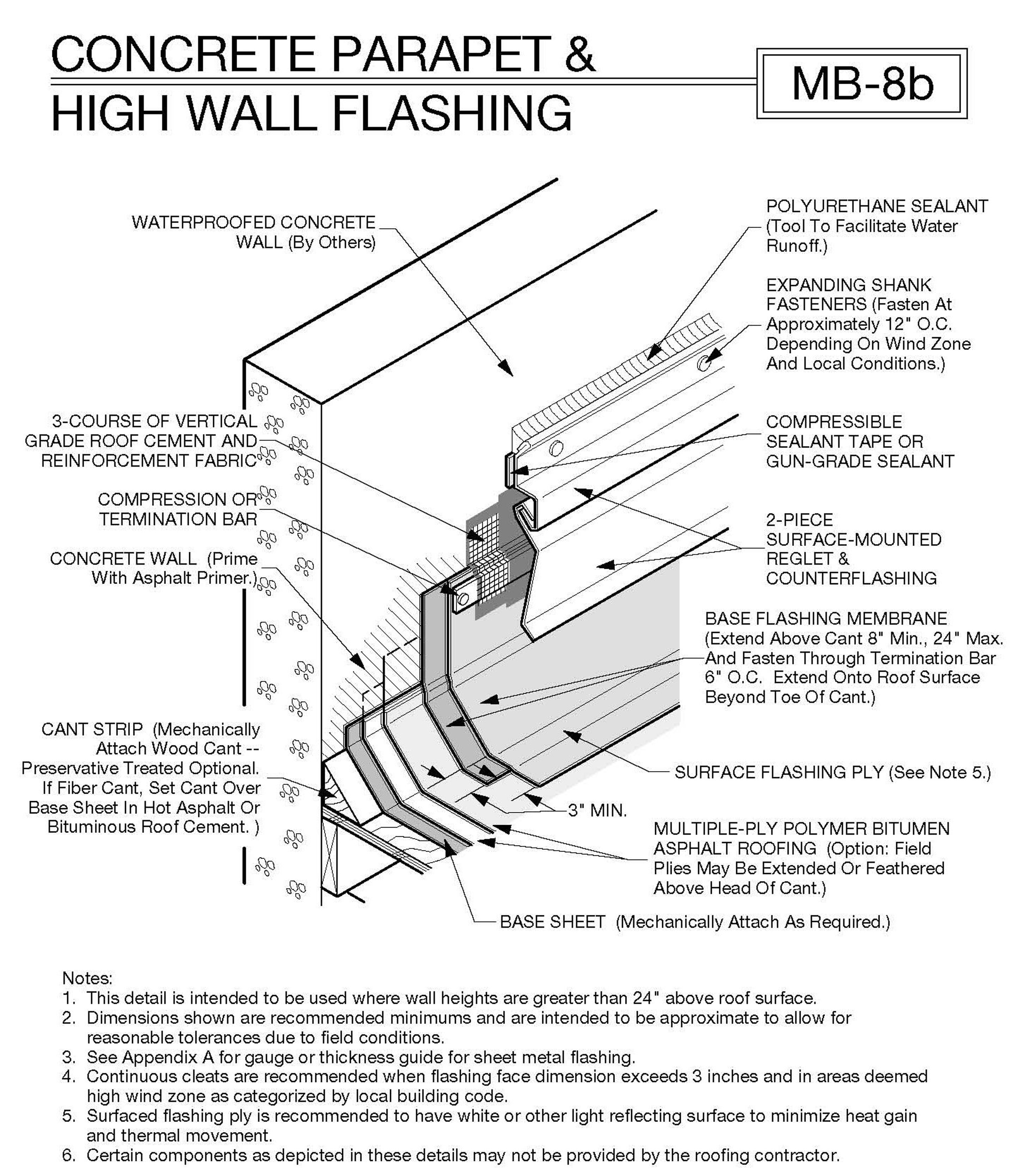
In situations where the parapet wall extends above the maximum 12-inch flashing height and wall waterproofing is required, there are several options. In the case of concrete or masonry walls, waterproofing can be provided by the installation of a membrane covering, a metal covering or a waterproofing coating. (See Figure 2.)
If the designer chooses to apply a waterproofing membrane, the following design techniques should be adhered to:
• In cases where a modified bitumen sheet is used for flashing, it is a best practice to apply a second membrane flashing as the wall flashing. This material shall be applied over above the existing flashing, which should not extend above 12 inches up the wall. The flashing height is maximized due to the weight of the modified sheet and the susceptibility of slumping.
• Attach a termination bar over the roof flashing to decrease possibility of slumping.
• Apply the wall flashing over the roof flashing and termination bar. Both the wall flashing and roof flashing should be fully adhered to the wall substrate.
• Fasten the wall flashing at the top of the wall every 6 inches on center.
• Apply a coping over the wall flashing and fasten with self-tapping screws every 24 inches on center.
Interior Drains
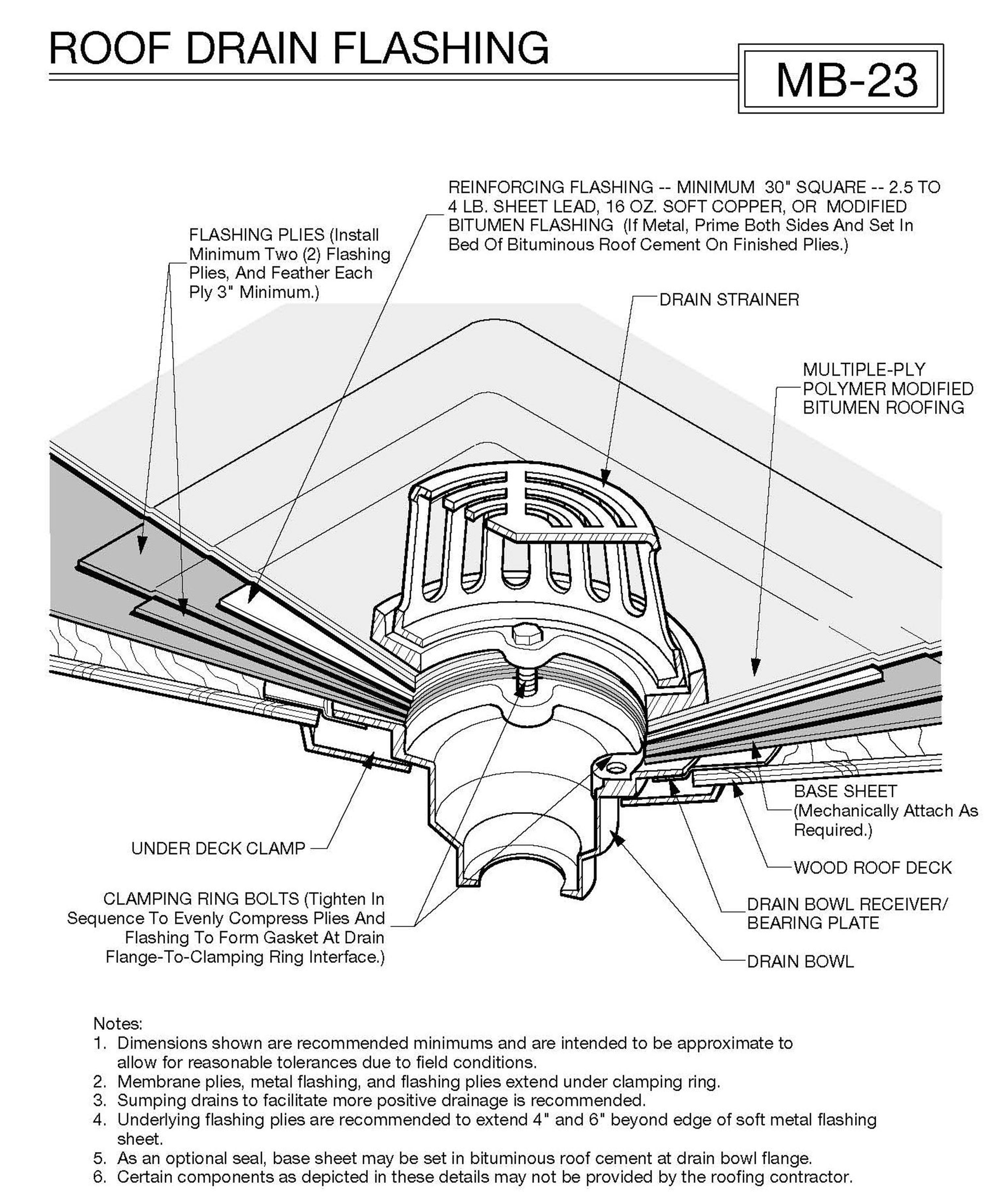
Roof drains are provided throughout the roof to remove water from the roof surface. The National Roofing Contractors Association and most membrane manufacturers require the removal of ponded water from the roof surface within 48 hours after a rainfall. This is accomplished by locating internal drains at low points of the roof or at points of maximum structural deflection.
The number of drains required is determined by completing a roof drain calculation that takes into account the size of the roof area and the slope of the roof, among other factors. The most important factors in drainage design are:
• Properly slope the structural framing and deck (minimum 1/4 inch per foot).
• Use an insulating fill or tapered insulation for slope.
• Properly locate roof drains, scuppers and gutters to remove water from the roof’s surface.
• Recess the drain below the roof surface.
• Design saddles or crickets to create positive drainage to the drain.
• Provide extra insulation around the drain head to prevent condensation.
Materials used should be consistent with the roof membrane manufacturer’s requirements. Prior to installation, flood all drains to determine if they are in working condition. All drains shall be covered during installation to safeguard from bitumen flow. (See Figure 3.)
Taper roof insulation around roof drains evenly over an area 4 feet by 4 feet to aid drainage. Add a tapered edge strip to create a smooth transition. Install a 36-inch square copper flashing at each sump, set on finished roofing felts in adhesive. Apply a new two-ply strip in of membrane and adhesive at the perimeter of the copper. Roofing plies, copper flashing and membrane shall be secured under the clamping ring of the roof drain. Install new drain strainers.
Accessory Problems
Rooftop equipment is a primary source of problems, particularly at flashing seams. Problems at flashings are often due to improper or poorly designed details. Problems can also result from movement due to operation of the equipment. Chemical discharge from certain rooftop equipment can quickly degrade a roof membrane. The equipment discharge must be controlled with proper design and maintenance products.
Problems at penetration and termination structures are chronic leak sources. With pitch pans, problems are often due to the loss of fill material, hardening of the fill material, and construction away from the support during the cold cycle. Improper terminations between the roofing membrane and penetration structures are difficult to assess and correct because of the multitude of installation variables.
Industrial facilities use the roof system as a “floor” for gas lines, antennas, satellites and other cumbersome equipment. All of these accessories are laid on the roof membrane. Sometimes the proper support pads are provided. However, most of the time the equipment or pipes are set directly on the membrane or with only a slip sheet under them. We have also observed this type of equipment set on concrete pavers. Over the years, the weight of the equipment, pavers or pipes may dig into the membrane and create openings and splits. If the slip sheets are loose laid under the support, they tend to blow away or move from under the equipment, leaving the membrane exposed to the equipment. Proper supports could eliminate these problems. In the case of pipe support systems, be certain that the installed supports do not penetrate the membrane.
We have also observed electrical lines that were partially buried in the roof system or set through roof openings with little attempt to provide a detail. Obviously, the wires should be set above the roof surface and an access through the roof surface should be accompanied with a pitch pan or tubular penetration detail.
Sealants applied at metal joints (at any point within the roof system) should be considered maintenance items. Sealant failure accounts for the majority of roof leaks that occur at metal terminations. Properly applied sealants will typically last three to five years in these constructions.
These are a few of the details that we have observed concerns with over the years. Making sure these details are designed and installed correctly can prevent leak calls down the road. In re-roofing situations, it’s crucial that the details reflect the as-built conditions of the roof system. A little extra attention during the design and installation process can prevent emergency repairs and result in a big boost to the bottom line.
Looking for a reprint of this article?
From high-res PDFs to custom plaques, order your copy today!
.webp?height=740&t=1767036885&width=auto "Header - BE 1170x658 (002).png")

.webp?height=740&t=1755781744&width=auto "KEE(2).png")