Critical Areas for Waterproofing

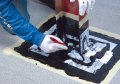
Installation of flashing should be completed in accordance with the manufacturer’s latest printed specifications. (Photo courtesy of Johns Manville.)
The main function of a structure is to protect man from the environment. Advancements in material technology, application procedures and design have not changed this function. The main purpose of waterproofing is to serve as a barrier that protects the interior of the structure from moisture intrusion and other environmental ingress. Below-grade building components are susceptible to moisture intrusion because they can be exposed to moisture from groundwater for weeks - even months - at a time. Buildings constructed in low-lying areas with high water tables can be exposed to groundwater throughout the life of the structure.
There are several points where a below-grade exterior component is prone to moisture infiltration. These points require proper design diligence from architects to keep moisture out of the building. Some of the more common areas of concern include:
• Penetrations.
• Cold joints.
• Expansion joints.
• Internal drains.
• Structural connections.

Proper installation of flashing at penetrations, equipment supports, joints and structural connections is
essential. (Photo courtesy of Johns Manville.)
Penetrations to subsurface structures are usually required at walls and deck substrates for pipes and conduits that are associated with mechanical equipment. The penetrations can be cast in the substrate (concrete or masonry) or they can be installed in sleeves. Most waterproofing experts would agree that placement in sleeves is preferable to casting them into the substrate for two reasons:
1. Sleeves provide for independent movement of the pipes, eliminating related cracks and fractures caused by movement in the structure.
2. Sleeves eliminate the need for several trades and simplify the whole process.
Installation of flashing at the sleeves should be completed in accordance with the waterproofing system manufacturer’s latest printed specifications.
The pipes and pipe sleeves should never be spaced closer than 6 inches to allow room for the flashing application. For bentonite systems, the penetrations are packed with troweled-on bentonite. On single-ply, built-up and liquid-applied waterproofing systems, the flashing can be completed with strips of the suitable bituminous or rubber membrane with approved adhesives. Typical flashing application involves two or three applications of the flashing wrapped around the penetration, with each successive application extending 2 inches to 3 inches beyond the previous application. A lead collar is applied and secured with a stainless steel drawband.
Conduits should be spaced a minimum of 6 inches apart. However, in most instances the space is limited and conduits are grouped together in a gang configuration. There should be a 1-inch diameter between the sleeve wall and the conduit or cable for concrete application around the sleeves to secure them in place. The membrane must lap the joint between the wall and the backout by a minimum of 2 inches. A sheet metal form is then applied over the membrane and around the penetrations and is set 1 inch from the wall. The sheet metal form is sealed with urethane on singleply, built-up and liquid-applied waterproofing systems, and with the mastic component on bentonite systems.
Flashings applied at penetrations must accommodate differential movement between the substrate (slab) and the pipe conduit. This can be achieved by filling the area between the pipe and the sleeve with a precompressed open sealant. The inner space can be filled with a Link-Seal, which is forced tightly against the pipe with bolts.
The disadvantages of sleeves are that they can contribute to condensation and flashing joints are prone to openings.
Flashing at penetrations and expansion joints is critical. (Photo courtesy of Johns Manville.)
All materials are subject to thermal expansion and contraction that is created by temperature changes. In waterproofing systems, there also exist structural sources of movement due to the large percentage of concrete substrates involved. Differential settlement and movement occurs from natural shrinkage of poured concrete. Thermal allowances have an effect on lateral movement of joints, whereas differential settlement affects vertical displacement. Tension and shear stress result in the joints from the induced strain created by the movement.
Joints in a concrete surface can appear as cold joints, shrinkage joints, control joints and expansion joints. Each joint has a specifically designed use in building construction for the control of cracking, vibration and various other movement factors. To achieve proper waterproofing of these joints, careful consideration must be given at the design phase. Most manufacturers have designs and required materials for construction joints. In all instances, the joint design should be in accordance with the manufacturer’s latest printed specifications.
Cold joints: Cold joints, also commonly referred to as construction joints, occur in sequential order from concrete placement of walls or structural slabs or at the intersection of walls and footers and at the intersection of walls and structural slabs. Waterproofing treatment of these joints should be completed prior to the application of the waterproofing system. Waterproofing of cold joints can occur by applying a double strip of flashing material over the joint or by applying a thin (⅛ -inch by ¼ -inch) strip of butyl sealant tape over the joint prior to the double strip of flashing material.
Shrinkage joints: Shrinkage joints are designed to control cracking during the cure of castin- place concrete. These joints are reinforced with wire or rebar and they are normally filled with concrete after the original concrete pour is cured. Although there is usually little or no movement associated with these joints, they are capable of creating plane shear transference to the waterproofing system, and they should be treated in the design phase.
Control joints: Control joints are designed to control cracking in the cast-in-place concrete that can occur from stresses exerted during the cure and from building movement that can occur after the pour. Movement is typically minimal, reserving cracking to the same plane as the rest of the cast-in-place concrete. Waterproofing is achieved in a manner similar to that used for cold joints by applying a ⅛ -inch by ¼ -inch strip of butyl sealant tape over the joint prior to the double strip of flashing material. Sealant tapes of other sizes to anticipate movement should also be considered.
Expansion joints: Expansion joints are structural separations (openings) that occur between two building elements. They are designed to accommodate the free movement of building elements without damage to the waterproofing system. When properly designed and applied, expansion joints will allow for movement in three destinations: perpendicular and parallel to the joint in the horizontal plane, and perpendicular to the deck in the vertical plane. They are an integral part of the structural system and are designed to reduce stresses caused by temperature fluctuations, possible differential foundation settlement and movement between different building materials.
Expansion joints are constructed of a minimum 1-inch to 2-inch wide separation that continues through the entire building from the rooftop to the foundation. Since independent movement of each building segment is required, double, parallel columns and beams are constructed on each side of the expansion joint to provide proper structural capacity.
Proper detailing and application of expansion joints at the waterproofing component is required to eliminate splitting and water intrusion at these openings. The most important design aspect of the expansion joint is that it must extend across the entire width of the area. Expansion joints that terminate short of the full area width or erroneously provide openings for drainage will fail to accommodate expansion and contraction creating membrane openings that could lead to waterproofing failures.
Expansion joints can be up to 100 to 300 feet in length, depending on the size of the building. There can be considerable movement in these large of spans, with movement within a range of ½ an inch to 1½ inches. The edges of the expansion joint should be raised so that the assembled joint is above any ponded water. This is accomplished when the joint is elevated a minimum of 1 inch or more above the substrate surface.
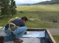
Here, Permaflash is applied on the roof of the Johns Manville Technical Center in Littleton, Colo. (Photo courtesy of Johns Manville.)
Internal drains should be installed when the area is very large or contained. If the water must travel a minimum of 40 feet to reach a drain, then interior drains should be installed. Also, if the area is contained by four walls - as in the case of planters - and no water runoff is afforded, then interior drains are required. The key element in designing waterproofing at interior drains is ensure that the waterproofing system is integrally tied in to the drains.
Lead reinforcing is required when the drains are installed in sleeves. If the drains are cast into the wall or slab, lead reinforcement is not required. Cast iron drains, cast into the slab with flanges flush with, or slightly below, the slab typically perform better in belowgrade conditions than aluminum, plastic or sheet metal drains. Cleanouts are required at all drains to avoid clogging caused by soil, gravel or contaminants. Drains used in below-grade construction are similar to roof drains and detailing is similar. These types of drains are best suited for sheet and liquidapplied membrane systems.
An additional layer (or ply) of material should be applied at all drain locations. For other systems, the use of composite materials is required. Be certain that the drain detail is in accordance with the manufacturer’s latest printed specifications.
Structural Connections
Structural connections can be a source of differential movement from the joining of two dissimilar materials. This condition exists at the junction of the horizontal substrate and the vertical wall (poured concrete or reinforced masonry block). Attachment of these materials is completed through the use of reinforcing bars or weld clamps that are not continuous. Therefore, movement is possible. The joints should be properly waterproofed with a flexible sealant (or butyl tape) and backer rod system. The waterproofing flashing is then applied in accordance with the manufacturer’s requirements.
Looking for a reprint of this article?
From high-res PDFs to custom plaques, order your copy today!
.webp?height=740&t=1767036885&width=auto "Header - BE 1170x658 (002).png")

.webp?height=740&t=1755781744&width=auto "KEE(2).png")