What it Takes to Execute a Successful Recladding Project
A Case Study on Investigating Deterioration and Providing Repair Recommendations

Figure 1. One M&T Plaza Building – West Elevation (Photo taken in 2015). All photos courtesy of SGH.
Minoru Yamasaki was a Japanese American architect who rose to prominence in the early 1960s with his distinctive blend of ornamental and modernist architecture. In 1963, the Manufacturers and Traders Trust Company (M&T) commissioned Yamasaki to design their new office building in Buffalo, New York. Completed in 1967, One M&T Plaza is a 22-story tower rising from a landscaped plaza encompassing a full city block. The ground level features a 35-foot tall lobby originally clad with 3 cm thick, Vermarco Taconic white marble accenting full‑height, arched windows along the east and west elevations (Figure 1). The north and south elevations featured bookmatched, 3 cm thick, Vermont Verde Antique green marble panels framed by Vermarco Taconic white marble (Figure 2), and the top of the ground floor at the north and south elevations is capped with curved stone soffit panels creating an offset from the upper floors forecasting Yamasaki's later design at Rainier Tower.
Over the building’s life, the lobby-level facade performed well despite underlying material and detailing deficiencies that were unknown in the industry at the time of construction. As was common to other thin marble veneer construction of this era, cracking and bowing of the white panels was prevalent and included cracks and corrosion staining on the green marble emanating from embedded reinforcement, resulting in continually increasing maintenance demand. Previous panel replacement campaigns were generally unsuccessful as the replacement marble was not a good aesthetic match for original marble and the replacement panels exhibited similar signs of material degradation. M&T desired a solution to reduce the effort associated with this ongoing maintenance and mitigate the risk of a panel falling while maintaining Yamasaki’s original design intent.
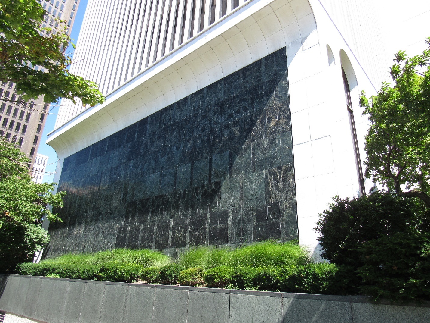
Figure 2. One M&T Plaza Building – south elevation (photo taken in 2015).
Assessment
In 2015, M&T contracted with Wendel WD Architecture, Engineering, Surveying and Landscape Architects (Wendel) and Simpson Gumpertz & Heger inc. (SGH) to investigate the cause of the observed deterioration and provide repair recommendations. The investigation involved a visual survey to identify discernible deterioration patterns and exploratory openings to observe the cavity construction and panel anchorage.
The visual survey confirmed that a significant number of the white panels were bowing (Figure 3) and the bowing was likely driven by hysteresis, a common issue for thin white marble claddings. The green panels exhibited cracking in two general patterns either aligning with stone veining or at a consistent distance from the panel edge (Figure 4). Exploratory openings at the green marble confirmed that cracking that did not align with a vein within the field of the stone was the result of corrosion of embedded steel reinforcement, suggesting water infiltrated the cavity through the panel joints.
Through exploratory openings, we also confirmed the configuration of the panel support system, which comprised stainless steel shelf angles (gravity anchors) every three or four stone courses (12 to 16 feet) and disc anchors at the top and sides of the vertical and curved panels (lateral anchors). At many locations, we observed spalls where anchors engaged the stone at kerfs cut into the panel edges. The cavity air gap varied between 1-inch and 3-inch thick with the cavity space filled with clay tile or mortar at some locations.
Considering the extent of deterioration and unsuccessful attempts to replace individual panels, the design team recommended a full facade replacement at the lobby level.

Figure 3. Bowed white marble panels (photo taken in 2015).
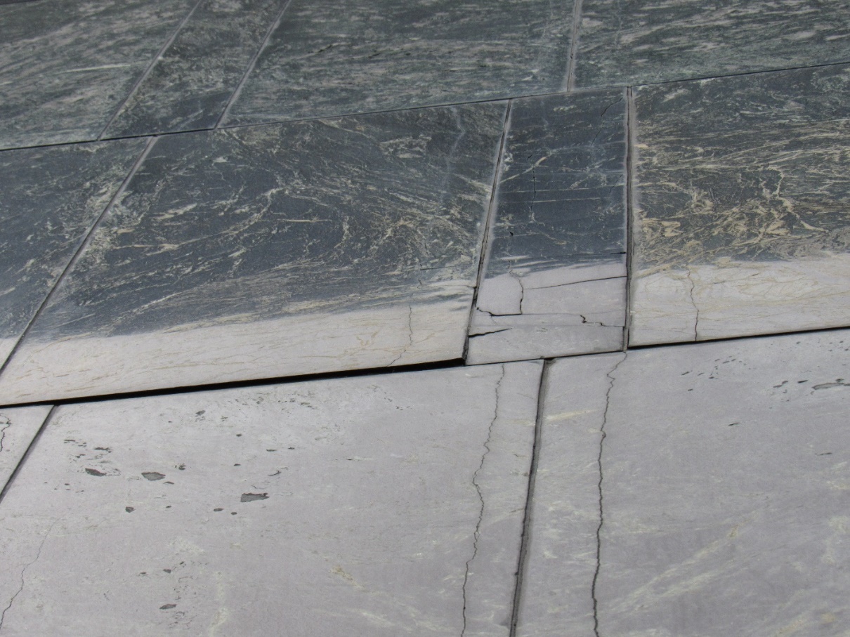
Figure 4. Cracked green marble panels (photo taken in 2015).
Note that cracks manifest a consistent distance parallel to the panel edge.
Facade Replacement Material Selection
M&T challenged the project team to provide marble replacement options that would be durable while respecting Yamasaki’s original design intent. The team presented several options for both the green and white marble that considered material properties, aesthetics, cost, fabrication limitations, and track record of successful in-service performance in similar climates. Figure 5 shows a series of full-scale mockup panels presented to M&T.
Options for the green panels included marble, granite, composite stone veneer (Stonelite), glass-fiber-reinforced concrete (GFRC), and metal panels. Ultimately, the original Vermont Verde Antique marble was selected utilizing a 4 cm thick panel (1 cm thicker than original). The use of thicker panels reduces the risk of hysteresis and eliminates the need for embedded steel reinforcement, which caused significant cracking in the original stone panels. The team visited two Chicago projects constructed in 1961 and 1983 with Verde panel veneers in similar thickness to the proposed replacement panels that exhibited minimal panel cracking. Also, the new panels would be supported individually rather than every three to four courses, which would reduce stress concentrations at the kerf anchors. The marble also provided the finish and dark green with a white veining pattern that maintained the original design aesthetic.
The team evaluated similar options for the white panels including granite, GFRC, metal panels, and crystallized glass ceramic panels. Granite has been successfully used in similar marble reclad projects; however, the white panels with black and gray grains was a poor aesthetic match for the Vermarco Taconic marble. GFRC offered custom color and texture matching abilities, but ultimately chose glass ceramic panels because of their high strength, installation ease, fabrication flexibility, and successful use on projects in Kansas City and Ottawa. M&T selected the Japanese-manufactured Neoparies glass ceramic panel as it was able to achieve the closest aesthetic match to the original white marble.
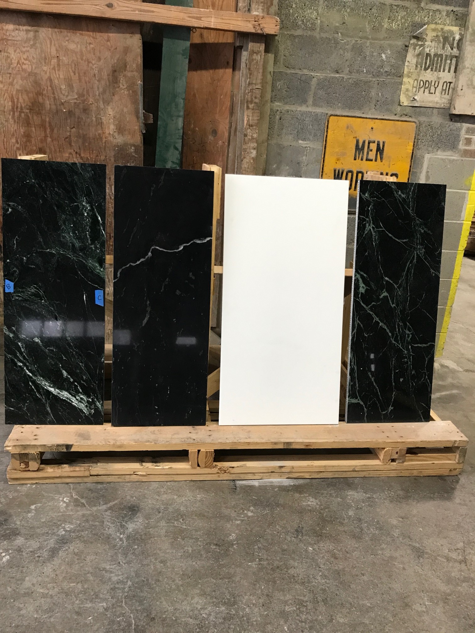
Figure 5. Sample panels.
Left to right: Vermont Verde Marble, Ritz Verde Marble, Neoparies, and Stonelite.
Considering the desire for a strong aesthetic match to the original stone, the team developed a material testing program to better understand the crystallized glass properties and compare it to the granite and marble options. SGH performed absorption testing, microscopic evaluation, flexural strength, and anchor testing on the Neoparies panels (Figure 6). The panels had properties in each of the tested categories that met or exceeded that of granite and the original marble, indicating that they were suitable candidates for the replacement panels. Similar testing was performed for the green marble to determine design properties for the repair design.
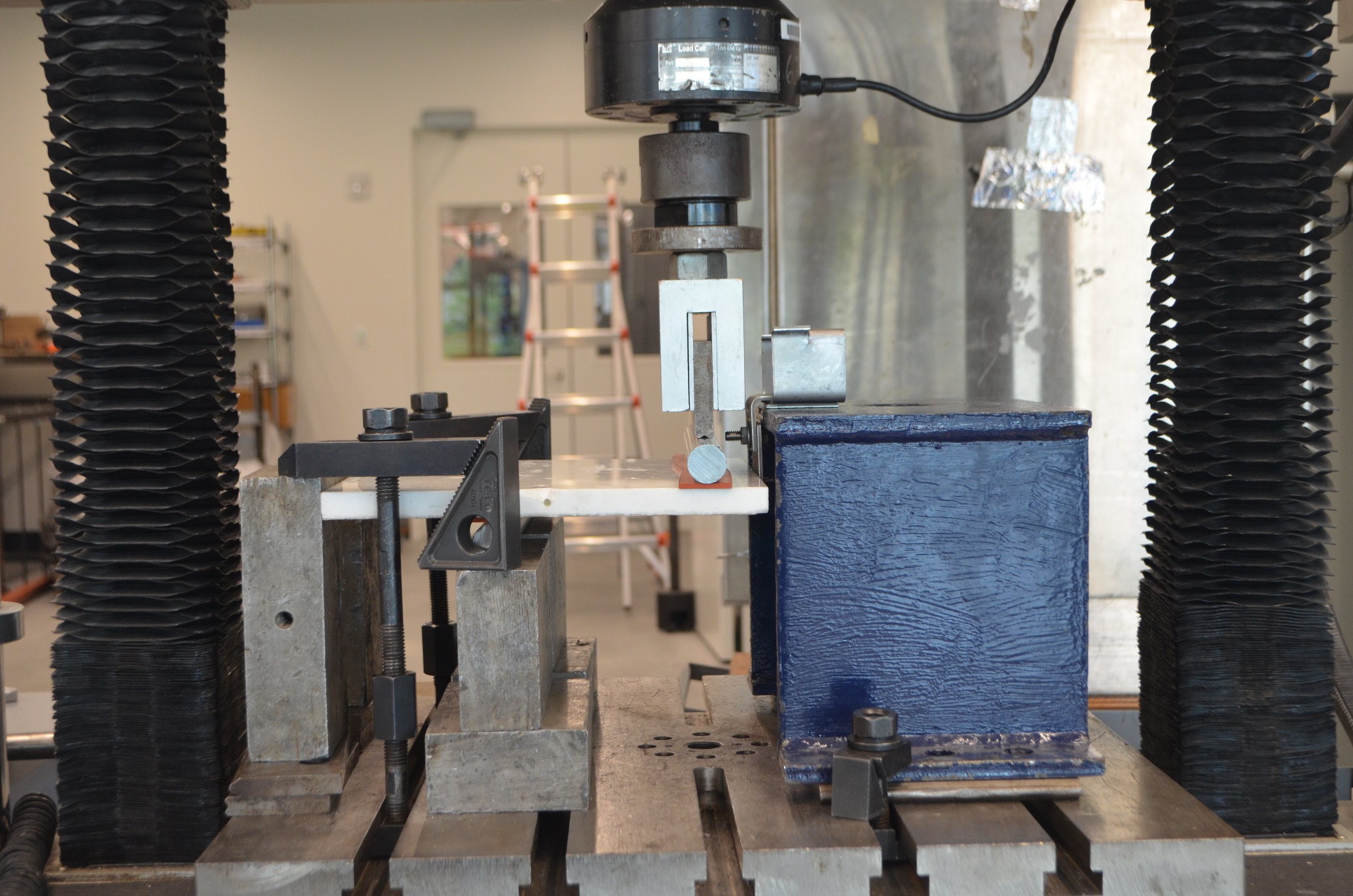
Figure 6. ASTM C1242 Anchor Testing on Neoparies Dowel-Type Anchor
Recladding Design and construction
In 2020, SGH and Wendel developed the recladding design for the replacement panels, anchor supports, and backup structure waterproofing. The basis of design followed the recommendations in ASTM C1242 and physical testing results. Key design components included supporting each facade element independently, utilizing stainless steel anchor components, detailing custom anchor plates to accommodate existing backup construction, and using a variety of split-tail kerf, dowel, and undercut anchors to match the original jointing and curved panel geometry.
The typical green panels are supported with staggered split-tail anchors set in kerfs along the panel edges. To match the original panel jointing, the smallest green panels (6-inch wide) were connected to larger panels with back-mounted stitch plates and T-shaped slotted undercut anchors (Type 31). Figure 7 shows the lowest course of the green panels on the north elevation and a typical stitch plate detail. The panel design utilized the preconstruction flexural strength and anchor testing results to determine the panel thickness and anchor size and spacing. The flexural testing identified a large variation in the stone flexural strength between orthogonal directions. One direction had a strength that was approximately 25 percent of the strength of the other direction. This is due to the significant veining of the stone and was likely the reason for the steel reinforcement rods in the original stones. To allow flexibility for the stone fabricator to choose vein orientation relative to the long axis of the panel and eliminate the potential for stone damage from flexural stress, the design team utilized the lower strength in the design.
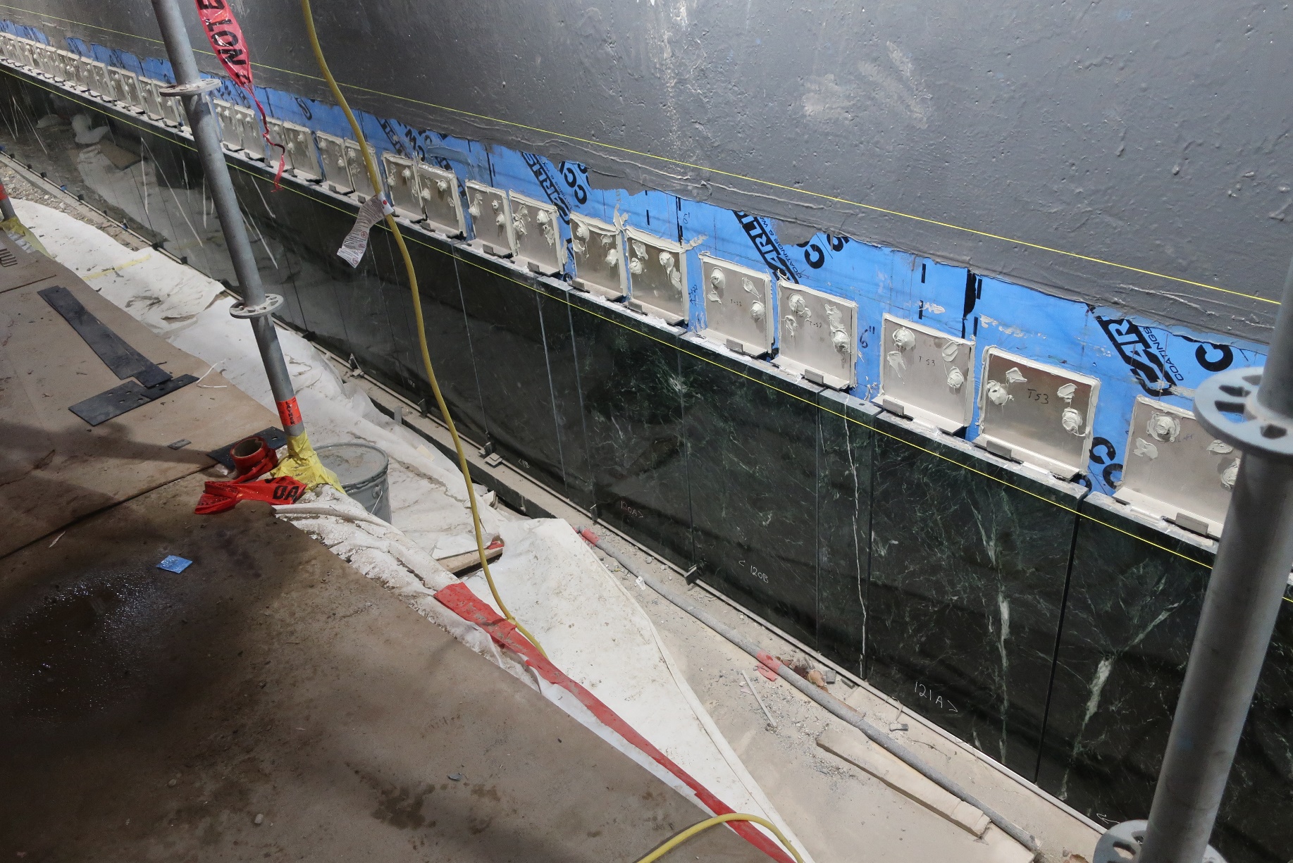
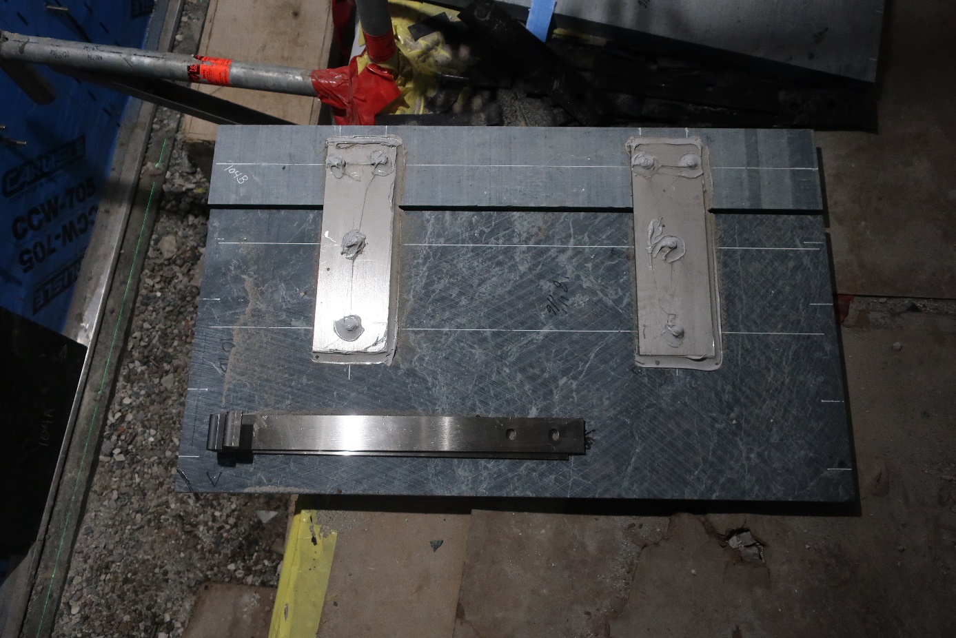
Figure 7. Vermont Verde panel installation (left) and stitched panel hardware (right)
The vertical Neoparies panels used the manufacturer’s standard dowel-type pin detail set into a drilled hole in the edge of the 16 mm panels. Overhead and curved panels used a custom assembly of back-mounted undercut anchors, shims, and plates to create external slots for both gravity and lateral connections. Figure 8 shows the curved panel installation at the top of the lobby-level facade utilizing serrated anchor plate assembly set in the exterior slots.
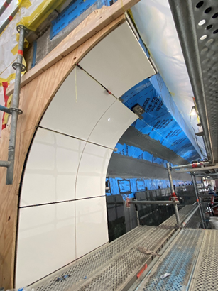
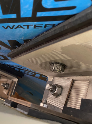
Figure 8. Neoparies curved panel installation (left) and back-mounted undercut anchor detail (right).
Repair projects are notoriously difficult to establish standardized details since as-built construction can vary from original design drawings. With this in mind, the design team incorporated several features allowing the contractor flexibility to make adjustments in the anchor hardware to account for a wide range of substrate conditions without the need to contact the design team due to variance in the substrate; these included: 1) panel support brackets permitted shims to accommodate 1 inches of out-of-plane variation in the concrete substrate; 2) bracket plates were detailed with multiple holes allowing adjustment of the concrete anchor locations due to conflicts with existing steel reinforcement (Figure 7); and 3) slotted holes and serrated plate assemblies provided field tolerances in multiple directions (Figure 8).
The project progressed smoothly with few complications despite occurring during the COVID‑19 pandemic from its start in the winter of 2021 to facade completion in early 2023. As with many projects during the pandemic, material availability and procurement challenged the construction team. Buffalo Construction Company (Buffalo) and their stone subcontractor, Manning Squires Hennig, made exploratory openings during the planning phase to confirm the distance between the facade and the supporting wall behind to allow for fabrication of the stone brackets prior to the start of wholesale demolition to mitigate potential delays associated with fabrication. Once construction started, the variability in the condition of the concrete backup structure was significant requiring concrete repair work, grinding, and shimming. Despite the variability encountered by the construction team, the shimming remained within the design tolerances for the concrete anchors requiring no changes to the anchors or the brackets.
Also, SGH and Buffalo coordinated to establish custom details for anchoring the stone infill panels to be installed at scaffold tieback locations. The details used half-moon anchors welded to threaded rods. The anchors were set in the top kerf of the lower panel and rotated 90 degrees to engage the bottom kerf of the infill panel using a screwdriver in the panel joint.
Conclusions
A successful recladding project is usually only known by the project team, as the final product looks almost identical to the original product, just without the deterioration. The success of this project was driven by the diligence and attention to detail of all the parties: the owner to find the right material; the design team to develop the right details; and the construction team to execute the project and maintain the quality standards set by the owner and the design team. This partnership led to the ability to respect the original design intent of Yamasaki while updating to modern materials that would perform better than the original.
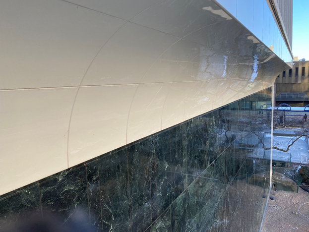
Figure 9. One M&T Plaza Building - North Elevation (Photo taken in 2023)

Figure 10. One M&T Plaza Building - West Elevation (Photo taken in 2023)
All photos courtesy of Simpson Gumpertz & Heger Inc.
References
ASTM Standard C880-18e1, 2018, “Standard Test Method for Flexural Strength of Dimension Stone,” ASTM International, West Conshohocken, PA, www.astm.org.
ASTM Standard C1242-18a, 2018, “Standard Guide for Selection, Design, and Installation of Dimension Stone Attachment Systems,” ASTM International, West Conshohocken, PA, www.astm.org.
Beasley, Kimball, “Marble Mistakes.” ASCE Journal of Performance of Constructed Facilities, May 2006: pp. 111-112.
Looking for a reprint of this article?
From high-res PDFs to custom plaques, order your copy today!
.webp?height=740&t=1767036885&width=auto "Header - BE 1170x658 (002).png")

.webp?height=740&t=1755781744&width=auto "KEE(2).png")