Waterproofing Penetrations 101
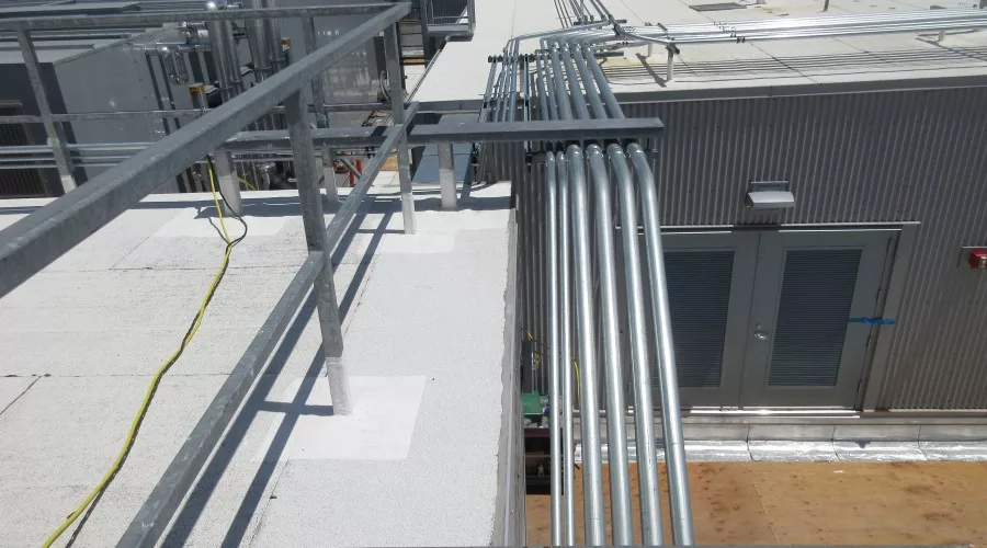
Figure 3. By-the-book" roof penetrations with watertight seals. All images courtesy of Simpson Gumpertz & Heger.
Utilities, signage, lights. Penetrations through exterior building enclosures are unavoidable. These penetrations serve critical functions for facility owners and occupants but can cause water intrusion. If a penetration is coordinated, detailed, and installed properly, it will achieve its desired result without creating unintended performance issues.
Since penetrations are unavoidable, all waterproofing manufacturers have a standard penetration detail (Figure 1).

Figure 1 - Conceptual detail for penetration through below-grade waterproofing membrane.
The waterproofing concept illustrated in Figure 1 for below-grade penetrations is very straightforward: lap the waterproofing membrane onto the penetration to create a seal between the waterproofing membrane and the penetration. While Figure 1 is an illustration for below-grade waterproofing, the same concept applies to exterior walls when rotated 90 degrees, and to roof, podium, and terrace waterproofing when rotated 180 degrees. Figures 2 to 5 are examples of penetrations through the below-grade, roof, podium/terrace, and exterior walls that match the generic waterproofing concept shown in Figure 1.
 Figure 2 - "By-the-book" below-grade penetrations with watertight seals.
 Figure 3 - By-the-book" roof penetrations with watertight seals.
 Figures 2 to 5 are all "by-the-book" circular pipe penetrations that are in strict accordance with the waterproofing manufacturer's standard penetration detail. On any typical project, 95 percent of the penetrations are by-the-book and will follow the waterproofing manufacturer's standard detail. The remaining 5 percent of the penetrations will come in all forms and shapes. Waterproofing manufacturers do not typically provide standard details for atypical penetrations. The remaining 5 percent,the uniquely shaped penetrations, are the focus of this article.
Base on the "by-the-book" single pipe penetration depicted in Figure 1, there are three fundamental features that will serve as the three general guidelines for adjusting penetrations to achieve a watertight seal:
Guideline #1 - Clear Spacing
A single penetration is shown Figure 1. Sealing waterproofing membrane requires an installer to execute the manufacturer's detail. The installer must have access and clearance to apply, roll, brush, and tool the waterproofing material. If the penetrations are close together, that limits the installer's access, potentially compromising the execution of the seal, which may affect the detail's performance. When the penetration deviates from Guideline #1 - Spacing, a common strategy is to relocate the penetrations to provide sufficient clear spacing for the watertight seal.
 Left: Figure 4 - "By-the-book" podium penetrations with watertight seals. Right: Figure 5 - A "by-the-book" exterior penetration with a watertight seal.
Guideline #2 - Watertight
When attempting a watertight seal, the portion of the base material that is the substrate for the seal must also be watertight. This may seem obvious, but it is an important guideline to consider. Some construction materials are not inherently watertight. The most prominent below-grade example is a braided copper wire for a grounding system. A braided wire is formed by numerous smaller wires twisted together. Due to the lack of spacing between the wires (violating Guideline #1 - Spacing), the braided wire itself is not watertight; therefore, there is no reliable method to provide a watertight seal. When the penetration deviates from Guideline #2 - Watertight, a common strategy is to locally switch the non-watertight material to a watertight material (i.e., switch to an electrically compliant section of solid copper rod instead of the braided wire at the location of the watertight seal).
Guideline #3 - Sound and Solid
In addition to being watertight (Guideline #2), the penetration in Figure 1 is sound and solid. Examples of materials that are not sound, solid, or semi-rigid construction are flexible conduit, flex duct, and wires. Semi-rigid materials are susceptible to movement, which can tear the waterproofing membrane seal. When the penetration deviates from Guideline #3, a common strategy is to locally switch to a sound and solid material at the watertight seal (i.e., switch to rigid conduit instead of flexible conduit).
These three general guidelines for a successful watertight seal pertain to all penetrations through the exterior enclosure regardless of the penetration location. However, the penetration location affects possible waterproofing strategies due to differing environmental exposure at different locations around the exterior envelope enclosure. A brief review of the exterior enclosure environmental exposure is required prior to reviewing penetration examples.
Exterior Enclosure Environmental Exposure
In a below-grade hydrostatic condition, the structure's environmental exposure is analogous to being submerged in a swimming pool. In non-hydrostatic conditions, the below-grade waterproofing will experience periods where it is submerged in water from rainfall and other transient water sources, such as irrigation.
The building code requires overflow roofs drains (typically 2 inches above the primary drain) to facilitate drainage when the primary drainage is impaired. Overflow drains in roofs, terraces, and podiums limit the height of ponding water the roofing system will be exposed to.
Above-grade exterior walls are water-shedding surfaces. Unlike in the below-grade and on the roof, there is no expectation of ponding water.
Environmental exposure is a factor in how to adapt the three general guidelines for sealing penetrations at different locations in the exterior enclosure. The remainder of this article reviews example penetrations to show how the three general guidelines can be used to develop solutions for unique penetrations.
Below-Grade Waterproofing Examples (Figures 6 to 8)
Figure 2 has a "by the book" seal of two separate penetrations through the below-grade waterproofing membrane. Each penetration is a solid and rigid PVC pipe and complies with the three general guidelines of (1) having clear spacing, (2) being watertight and (3) being sound and solid. The waterproofing membrane wraps up the pipe per the manufacturer's standard penetration detail (Figure 1). However, the same PVC is not sealed watertight in Figures 6 and 7.
 Figure 6 - "By-the-book" exterior penetrations wrapped in protection tape. The waterproofing membrane is sealed to the protection tape, which is not watertight - violating Guideline #2 - Watertight
Figure 6 shows the same PVC pipes as Figure 2, but the pipes are wrapped with protection tape. Protection tape is common and may be required by mechanical and plumbing codes. However, the same "by-the-book" seal deviates from Guideline #2 - Watertight because protection tape is not watertight. When the waterproofing membrane is sealed to the protection tape instead of directly to the pipe, water can travel between the protection tape and the pipe itself, bypassing the waterproofing membrane into the interior. The design team must review whether protection tape can be removed at the waterproof interface for a long-term watertight seal for every project.
Figure 2 shows two pipes, where the waterproofing detail is successfully executed at both. In Figure 7, the two pipes are right next to each other, violating Guideline #1 - Spacing. The waterproofing installer attempted to waterproof two penetrations as one single penetration without sealing the gap between the two pipes. Considering the environmental exposure of below-grade waterproofing is subject to water submersion, one cannot expect watertight performance when the waterproofing seal is missing between the two pipes. The solution that will provide a reliable seal is to relocate one of the pipes to provide clearance between the two pipes. Therefore, it is good practice to establish a minimum clear spacing between penetrations, such as 6 inches minimum clear spacing. Once the minimum clear spacing requirement is established during the project's design phase, contractors are more likely to coordinate clear spacing between trades, report if penetrations must be spaced closer together, and allow the waterproofing installer an opportunity to review and effectively execute the detail.
 Left: Figure 7 - Two penetrations without clear spacing, violating Guideline #1 - Spacing. The waterproofing is wrapped around both pipes as a ganged penetration instead of individually. Right: Figure 8 - The waterproofing membrane is cut around the concrete forming tube and the conduit. Junction box supported by a concrete pedestal and concrete forming tube.
A photo of a unique penetration consisting of a small concrete pedestal form with a round concrete forming tube supporting an electrical junction box is presented in Figure 8. As photographed, the waterproofing membrane is installed to the conduit and the concrete forming tube per the "by-the-book" penetration details. The seal to the concrete forming tube is incorrect. The concrete forming tube is made up of cardboard. Cardboard is not watertight, sound, or solid and thus deviates from Guidelines #2 and #3 and is not a suitable penetration to interface with the waterproofing seal. A common strategy for a penetration that deviates from Guidelines #2 and #3 is to switch the seal to a suitably watertight solid material. The junction box itself is metal and thus satisfies Guideline #3 - Sound and Solid.
However, the junction box perimeter has numerous knock-outs for possible conduit connections. Knock-outs are discontinuities in the metal of the junction box. Discontinuous in the metal means the junction box is not watertight, deviating from Guideline #2 - Watertight. As neither the concrete forming tube nor the junction box are suitable waterproofing substrates, only the concrete pedestal remains. Concrete is porous, prone to cracking, and does not generally have watertight performance in a below-grade environment. There are no suitable penetration materials in Figure 8 because all the elements deviate from Guideline #2 - Watertight. One strategy is to switch the non-watertight materials to watertight materials, as in the below-grade grounding rod example. However, for the example shown in Figure 8, the best strategy is to avoid the penetration altogether. The penetration from the concrete pedestal can be completely avoided by running the waterproofing membrane continuously. In other words, use the concrete pedestal as a substrate for the waterproofing membrane by turning the waterproofing membrane vertically around the pedestal and then pass it between the concrete pedestal and the junction box, resulting in no penetration through the waterproofing membrane.
Below-grade waterproofing requires the penetrations to meet the three general guidelines without exception for a reliably successful seal. When irregularly shaped penetrations occur, the waterproofing solutions can be found by diagnosing how the penetration deviates from the three general guidelines and finding the solution that avoids the penetration altogether or modifies it to comply with all three general guidelines.
Roofing Examples (Figures 9 and 10)
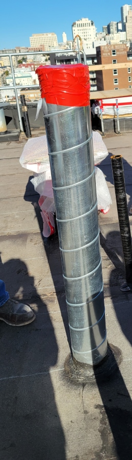
Figure 3 is a "by the book" roofing penetration. The penetration is far from other elements, is watertight, is sound and solid and as such complies with all three general guidelines. The roofing membrane upturns more than 8 inches onto the pipe in accordance with the roofing manufacturer's standard requirement. The penetration in Figure 9 (to the right) seems very similar to Figure 3, but due to the continuous open seam spirals along the entire penetration wall, the penetration is not watertight at any point in seam and thus deviates from Guideline #2 - Watertight. To create a watertight component, the project team used the roofing membrane's liquid flashing to seal the entire penetration shaft, sealing the spirals to the top of the penetration instead of the manufacturer's 8 inches minimum requirement.
Figure 9 shows roof penetration with spiral open seam in the wall of the penetration.
 A successful watertight seal to a roof penetration requires the penetration to comply with the three general guidelines. But due to the roof's open exposure, the design team can take advantage of solutions that provide shelter instead of a watertight seal to the penetration. The roof's environmental exposure permits alternative details for ganged-together penetrations, such as at an MEP "dog house" (Figure 10) and, in limited circumstances, a "pitch pocket."
Figure 10 is what is commonly known as an MEP "dog house." A dog house is a sheet metal enclosure to which the roofing membrane is sealed and serves as the substrate for the watertight seal without exception to the three general guidelines. The deviations from the three general guidelines all occur inside the sheet metal enclosure, but that is no longer within the plane of the roofing membrane. The termination of the roofing against the sheet metal enclosure is a standard roofing termination detail. The sheet metal enclosure takes the environmental exposure of the penetrations from the roof to the vertical water shedding plane. The sheet metal enclosure provides shelter for penetrations instead of a watertight seal. As long as the sheet metal vertical flanges allows for the required roofing membrane upturn, downturn of the sheet metal enclosure is sufficient to withstand wind-driven rain, the penetrations within the dog house can be expected to remain weathertight with limited required maintenance.
In a pitch pocket detail, the penetration through the roofing membrane is sheet metal box that is open to the sky. The sheet metal box is a penetration through the roofing membrane and allows for a watertight roofing membrane termination. The deviation from the three general guidelines all occurs inside the sheet metal box. However, the pitch pocket sheet metal is open to the sky and does not provide any shelter to the tightly spaced penetrations. Inside the sheet metal box, the pitch pocket relies on pourable sealant to provide the weathertight seal around penetrations. The sealant is subjected to direct rain and UV exposure and requires intensive regular maintenance. While an additional flexible topical fluid-applied membrane seal is often added over the pourable filler material as a means of redundancy, the pitch pocket detail is still a maintenance-intensive penetration detail.
It is important to note that both the dog house and pitch pocket details have moved the problematic penetrations from the roofing plane to inside the sheet metal box. The sheet metal box resolves the roofing membrane termination, but the issue with the penetration itself is not resolved. The problematic penetrations still exist, and the strategy for addressing them is reliable at the dog house detail and dependent on regular maintenance for the pitch pocket detail.
 Figure 10 - MEP Dog House penetration flashing solution
Penetrations through the roofing membrane that follow the three general guidelines can be successfully and reliably waterproofed. Sheet metal enclosures that comply with the three general guidelines can serve as the penetration to terminate the roofing membrane and house problematic penetrations that do not conform to the three general guidelines. Instead of a watertight seal for the problematic penetrations, the sheet metal relies on water shedding, air seals, and maintenance.
Podiums and Terraces Examples (Figures 11 to 14)
Figure 4 illustrates a "by the book" penetration through the waterproofing membrane on a podium. As the environmental exposure of podiums and terraces is similar to roofs, the considerations and detailing are the same. However, the rate of water shedding from a podium and terrace can be greatly reduced compared to a traditional roof depending on the permeability of the finish material and drainage strategy (i.e., soil versus pavers over pedestals). Depending on the finish material, the upturn height of the waterproofing membrane may need to be increased if the waterproofing manufacturer requires the termination to be above the water plane, which may be elevated to the top of the finish surfacing material.
 Figure 11 - Typical glass guardrail attachment detail.
Glass guardrails are a common design feature at podiums and terraces to maximize the exterior aesthetic while maintaining safety. The standard glass guardrail attachment requires the glass to be set inside a metal channel (typically aluminum or stainless steel), and the metal channel is then fastened to a concrete or steel curb (Figure 11). When this attachment occurs on a podium or terrace, each fastener is a penetration through the waterproofing membrane. A commonly proposed waterproofing detail for the fastener is to simply seal over the fastener head with sealant. When the fastener penetrates through the podium or terrace waterproofing membrane, sealing over the fastener head is pointless since that sealant is inside of the metal shoe and thus has zero interaction with the actual penetration in the waterproofing membrane.
Based on the three guidelines presented in this article to create a watertight seal, the penetration must (1) have clear spacing, (2) be watertight, and (3) be sound and solid. In the case of the glass guardrail in Figure 11, the fastener is the penetration. The fastener itself is watertight, sound, and solid. However, there is no clear spacing between the fastener, the metal channel, and the waterproofing membrane, which deviates from Guideline #1 - Spacing. Unlike the ganged-together PVC pipes in Figure 7 that could be relocated (or better yet, coordinated and installed with clear spacing), the fastener is the guardrail's structural connection; there cannot be gaps between the fastener and the metal channel. The connection in Figure 11 requires tight compression of the channel to the concrete substrate for load transfer and cannot be moved. The design team must implement different strategies then relocation to address the deviation from Guideline #1 - spacing to provide a watertight seal for the glass guardrail fastener.
Strategy 1: Avoid It (Figure 12)
The solution presented in Figure 8 for the junction box is to completely avoid penetrating the waterproofing membrane. This seems irrelevant to a glass guardrail attachment detail since the guardrail needs to be anchored to a suitable substrate. However, the guardrail anchorage is not required to occur at the waterproofing plane. Figure 12 is one example of the "avoid it" strategy. The penetration through the waterproofing is a tube steel utilizing a "by the book" waterproofing detail. The tube steel is capped watertight by a continuous steel angle to which the guardrail is anchored. The steel angle and guardrail attachment are both elevated above the plane of the waterproofing and thus avoid any interaction with the waterproofing membrane.
 Figure 12 - Glass guardrail attached to a continuous steel angle. Steel angle caps tube steels penetrations watertight. The tube steel have a "by-the-book" watertight seal.
Another "avoid it" strategy can be borrowed from concrete dobies used to support and provide concrete coverage for reinforcement dowels. Instead of anchoring the guardrail to the structural concrete, some type of concrete pedestal or curb can be locally cast at the guardrail attachment location. The waterproofing membrane is continuous underneath the concrete pedestal/curb, and all rebar dowels connecting the pedestal/curb to the structural concrete will need to be detailed per the waterproofing manufacturer’s requirements. With the waterproofing membrane continuous on the structural slab, the guardrail anchorage is moved off the waterproofing plane and avoids interfacing with the waterproofing membrane.
The design team should implement the "avoid it" strategy whenever possible to eliminate fasteners through the waterproofing membrane. Both examples of the "avoid it" strategy added overall height to the detail by adding tube steel or concrete pedestal/curb. The height increase from the added tube steel or concrete curb/pedestal may push the metal channel above the finish material and may be architecturally unacceptable on some projects and require another waterproofing strategy.
Strategy 2: Creatively Avoid or Relocate It (Figures 13 to 14)
Figure 11 is presented as the standard glass guardrail attachment, but there are numerous alternative attachment methods. The designers should work with the waterproofing membrane manufacturer, railing manufacturer, and structural engineer for an alternative attachment that can achieve structural performance requirements and provide a suitable and watertight surface for a watertight seal. Figures 13 and 14 illustrates two examples that were successfully designed and executed on projects. Both Figures 13 and 14 require embed plates into the structural concrete. The guardrail attachment plates are welded to the embed plates. Figure 13 has pre-welded studs on the attachment plate. whereas Figure 14 has pre-punched threaded holes in the attachment plate. In Figure 14, the attachment plate is in the vertical orientation to elevate the holes above the anticipated water level in a terrace with pavers over pedestals. In both examples, the waterproofing membrane terminates onto the attachment plate, which serves as the watertight component. In both figures, the fastener for the metal channel does not penetrate the waterproofing membrane. Figures 13 and 14 are just two examples to illustrate a strategy. Actual detailing is always project-specific since it depends on project-specific structural loads.

Figure 13 - Alternative guardrail attachment. Watertight seal is to the continuous steel embed plate with threaded dowels.
Similar to below-grade waterproofing and roofing applications, penetrations through podiums and terraces that follow the three general guidelines can be successfully and reliably waterproofed. Avoid penetrations that do not have clear spacing to execute the watertight seal by elevating the penetrations above the waterproofing plane or by introducing a watertight component for the waterproofing seal.
 Figure 14 - Alternative guardrail attachment. Watertight seal is to the continuous steel attachment plate.
Exterior Walls Example (Figures 15 to 19)
Figure 5 is a photograph of a "by-the-book" penetration through an above-grade exterior wall. This photo of an above-grade circular penetration was relatively difficult to find because countless unique penetrations are present on exterior walls compared to other locations of the exterior enclosure. Exterior wall penetrations often need to be both functional and respect the building's aesthetic. Take hose bibbs for example. The simple hose bibb in Figure 15 comprises the connection to the water pipe, which can utilize the "by-the-book" penetration. However, a simple hose bibb is not suitable for multi-unit residential or commercial projects due to security and aesthetics. Figures 16, 17 and 18 are all examples of different hose bibbs. These hose bibbs have a metal enclosure serving as a housing unit with an opening inside to connect to the water pipe. Instead of the "by-the-book" penetration of the water pipe, the hose bibbs in Figures 16, 17 and 18 are all more complex because of their particular housing unit, and each requires review of the actual hose bibb to develop a suitable detail.
 Left: Figure 15 – Simple Hose Bibb. Right: Figure 16 – Hose Bibb - Water pipe is pushed out beyond the exterior sheathing.
The hose bibbs' housing unit in Figures 16, 17 and 18 are all metal and thus comply with Guideline #3 - sound and solid. However, the hose bibb housing has an opening for the water connection and is therefore not continuous. The design team should also expect water inside the housing unit itself, as the water can be turned on without connecting a hose. Therefore, the housing unit is not watertight, deviates Guideline #2, and cannot serve as the penetration for a watertight seal. The watertight seal must occur at the water pipe same as the simple hose bibb. However, the watertight seal to the water pipe is complicated by the depth of the housing unit, which pushes the water pipe outward (Figure 16) or back (Figures 17 and 18) into the wall cavity. A material is required to span the two different planes. A sheet metal flashing will provide the watertight component for the waterproofing membrane termination and span the depth of the hose bibb to reach the water pipe and allow for the seal to occur at the watertight component. Flexible flashing tape suitable for spanning gaps and compatible with the wall waterproofing membrane may also be an option to seal to the water pipe.
 Left: Figure 17 – Hose Bibb - Water pipe is pushed into the wall cavity from the elbow in the hose bibb. Right: Figure 18– Hose bibb - Waterline is pushed into the wall cavity from the depth of the hose bibb.
In exterior walls, the addition of sheet metal collar flange assemblies is an effective strategy to use when the watertight component and waterproofing membrane are at different planes. Sheet metal collars can also be used to terminate the waterproofing membrane and house ganged, not watertight, not sound, or solid penetrations, including wires (Figure 19).
 Figure 19 - Sheet metal collar used to house the flexible wires and provide a proper penetration for the watertight seal.
Conclusion
Whether it is below-grade, at the roof, on the podium, terrace, at the exterior walls, penetrations that follow three general guidelines will result in a reliable, durable, and warrantable waterproofing seal. The three general guidelines for penetrations are:
1. Clear Spacing: the penetration has clear spacing.
2. Watertight: the penetration has a watertight component.
3. Sound and Solid: the penetration is sound and solid.
When a unique penetration arises, the design team should review the penetration against these three general guidelines to diagnose the issue with the penetration that compromises the watertight seal. Avoid, relocate, modify or replace the problematic penetrations to a penetration that comply with the three general guidelines to allow for a more durable and long-term watertight seal.
Looking for a reprint of this article?
From high-res PDFs to custom plaques, order your copy today!

.webp?height=740&t=1767036885&width=auto "Header - BE 1170x658 (002).png")

.webp?height=740&t=1755781744&width=auto "KEE(2).png")