Sponsored by GAF | Siplast
CEU: More Than Just a Roof
Improving Energy Efficiency and Performance at the Roof for Schools and Hospitals
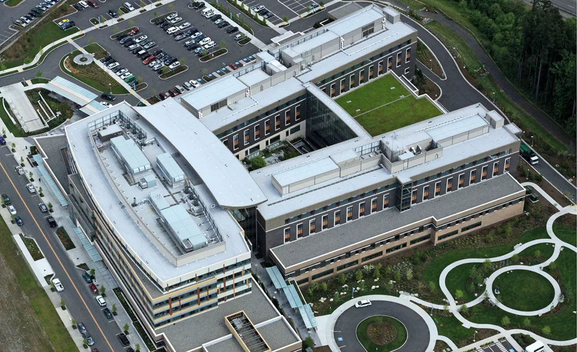
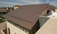
Photo courtesy of Siplast.
AIA course number: BE2023GAF2
Credit Type(s): 1 AIA LU/HSW; 1 IIBEC CEH; 0.1 IACET CEU
Learning Objectives:
After reading this article, you should be able to:
- Analyze design strategies to prevent moisture and air intrusion in schools and hospitals to protect occupant health, building integrity, and efficiency.
- Assess the importance of air, vapor, and thermal control design and layer continuity.
- Explain the interplay between air control, air barriers, and energy efficiency.
- Examine high-performance roof options for schools and hospitals, including membrane types and attachment methods that enhance energy efficiency.
Complete the quiz and receive a certificate of completion!


An elementary school in New Mexico faced a series of complex challenges with the roof: these included tight budgets, a short installation window, and an existing single-ply roof coming apart at the seams. To further complicate matters, the timeframe placed half of this project during New Mexico’s Monsoon Season. This required diligent planning, coordination, and scheduling to make sure everything on the site was covered and protected before the storms hit. Completing the project by the December goal also presented a challenge, as the selected fluid-applied system had to be installed and cured in temperatures of 50 degrees and rising. After thorough inspection and diagnostics, including an infrared thermography scan and moisture scans, the installer determined that several of the existing 11 roof sections had moisture trapped within the system and needed to be removed and replaced. The school’s new roof had to perform, be efficient, and to better the indoor air quality for its vulnerable occupants—the students. To meet these goals, new tapered ISO insulation and a peel-and-stick base sheet were selected, as well as a fully reinforced, fully adhered acrylic elastomeric system. The elastomeric system quickly rose to the top choice, based on its sustainable and highly rated nature. The new roof is energy-efficient, durable, was simple to install, did not require heavy equipment on the roof, is certified as low VOC, is easy to maintain, and comes with an excellent warranty. The selected system is also FM-4470 rated as a complete roofing system. These features and benefits were very attractive to Las Cruces Public Schools.
“Our roof project at Doña Ana Elementary School went exceptionally well. For such a major project, there was minimal impact on our learning environment. We were impressed that the noise level was minimal, and the smell of the product was hardly detectable. Student safety and learning was at the forefront of all decisions,” said Cherie Love, Principal, Las Cruces Public Schools.
Selecting the best roofing assembly for schools and healthcare facilities means focusing on project constraints including timeline, weather, facility operations, and occupants. Roof integrity and performance cannot be compromised as functionality, durability, and energy efficiency must come together to create the roof assembly that is best for each individual facility.
 The final complete roof system selected for Doña Ana Elementary School and installed by RoofCARE is energy-efficient, durable, and was simple to install.
Photo courtesy of GAF.
Scientific Principles in Efficient Roof Design
The built environment impacts the surrounding natural ecosystem, economy, occupant health, and productivity. Practices targeting energy efficiency and resilience can substantially reduce or eliminate negative environmental impacts and improve existing unsustainable design, construction, and operational practices. For healthcare and educational facilities, one can argue that practices that impact occupant health are paramount.
When designing an assembly for educational and healthcare facilities, it is critical to consider all elements of high-performance roof design. Efficient design can lower a building’s operational costs, increase building values, protect assets, and increase profits. It also can improve employee productivity and satisfaction, reduce sick days, and contribute to the building’s sustainability goals. Efficient buildings may enhance air, thermal, and acoustical quality, improve occupant comfort and health, and advance overall quality of life.
The roles of efficiency are met by different layers in the envelope assemblies, whether they are roof, wall, or foundation. No longer “just” a roof to keep precipitation out, today’s roof has many roles. For the high performance roof, these include effectively handling temperature and thermodynamics, relative moisture risk, and uncontrolled air. Failure to plan for even one of these elements, or planning incorrectly, frequently results in energy loss and inefficient operations. Efficiency, from a practical sense, can be related to HVAC demands, which ultimately impacts monthly heating and cooling bills. For hospitals and schools that typically have large building footprints, controlling energy efficiency can have a substantial impact on the bottom line. Incorporating high-performance systems, including the roofing assembly, can contribute to the overall energy efficiency of the building.
One of the primary purposes of a building enclosure, which is inclusive of all six sides of the building, including the roof, is to keep moisture out of a building. What makes this difficult is that moisture comes in many forms and can take many paths into a building. Building designers need to account for bulk water, capillary water, air-transported moisture, and water vapor, and must defend against each of these in different ways. For the wall of an enclosure, achieving a 100 percent successful water barrier is unlikely. Walls, with their many penetrations, including doors and windows, are difficult to make entirely “waterproof.” Good wall designs accept the fact that some water ingress might occur and include a drainage path down and then out of the structure without damaging it. This, however, is untrue for the roof assembly. Roof assemblies must be watertight and designed so that water is not able to enter into it. The water control layer in roofing assemblies is the membrane. For hospitals and educational facilities, the tolerance for leaks is low, which amplifies the need for a high-performing building enclosure.
There is one rule that defines how heat, air, and moisture move—the second law of thermodynamics. In terms of building and roofing science, this simply means that: hot moves to cold, moist moves to dry, and high-pressure moves to low-pressure. Heat, moisture, and pressure always equalize whenever possible. While preventing water ingress was a primary function of the first building enclosures, keeping occupants secure from rain and snow—thermal control—keeping inhabitants from freezing in winter and roasting in summer became an auxiliary function. Today’s low-slope roof assemblies typically use an insulating foam such as polyiso to aid in temperature control. Good design is important so that the effects of thermal bridging and penetrations are accurately considered. There is not only a code requirement for continuous insulation, but it is a good practice to eliminate thermal bridges where interior conditioned air loss may occur. Student and patient comfort is critical in learning and recovery environments, and mitigating loss of conditioned air to maintain set temperatures is an important component.
Building science experts identify air leakage as a major impediment to achieving better energy efficiency for the building enclosure. Essentially, the goal of an air barrier (in warm environments) is to prevent the loss of conditioned air from the interior to the exterior and the introduction of warm, humid air from the exterior to the interior. Just as thermal control needs to take into account thermal bridging, a material that only blocks air is insufficient in and of itself. Instead, an effective air barrier acts as an interconnected series of materials spanning the entire enclosure. The requirement for a continuous air barrier is a code requirement, but it also assists in ensuring that the pressurized spaces stay pressurized appropriately. For hospital settings where negative pressure rooms are required, it is important that the room is sealed appropriately to prevent contaminants from exiting the room. The requirement for an effective air seal must be considered at the roof level, to ensure that there is no loss of pressure through the roof assembly.
In simplicity, the main control layers for a roof assembly consist of water, thermal, vapor, and air control. The roof membrane and thermal insulation play a pivotal role in water and thermal control. However, the use of air barriers and vapor retarders also has import for the roof and can be a source of confusion, particularly for high performance and energy efficient roofs. The order and sequencing of these layers is strongly influenced by roof edges, or terminations of the roof assembly. This means that how the roof is tied into, or connected with, the wall and its various control layers has a large influence on the order of the layers and which controls might be carried out by each layer. This is particularly the case when discussing air barriers and vapor retarders.
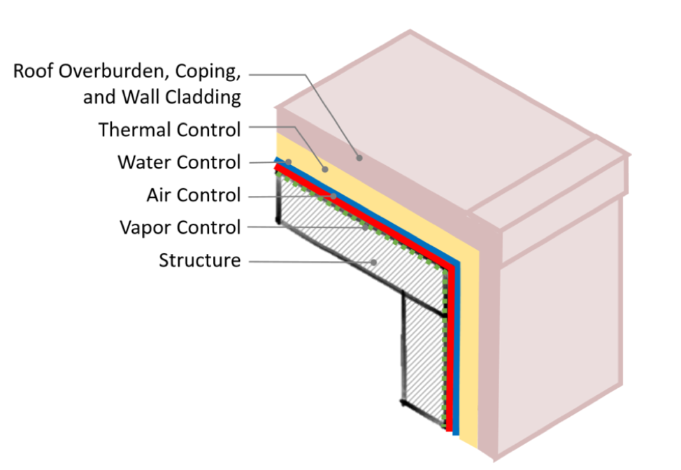 Simplified version of continuity of control layers from a roof to wall
Image courtesy of GAF.
As more materials and additional requirements are added to enclosures, including air tightness, it is important to recognize when materials and assemblies need to adapt in order to achieve higher energy performance. As energy efficiency is improved in building enclosures, moisture risks can increase from decreased heat flow and air movement across the assemblies. Unintended and uncontrolled air movement, vapor movement, and control layers that are not continuous across building enclosures can trap moisture within roofing assemblies. Proper design and installation is important to meet both performance and building code requirements. This is true for any facility, not just hospitals and educational buildings, although the risk associated with moisture in these structures could arguably be higher. Mold growth, which is a possible consequence of moisture, deteriorates indoor air quality (IAQ) and can be deadly for those with weakened immune systems.
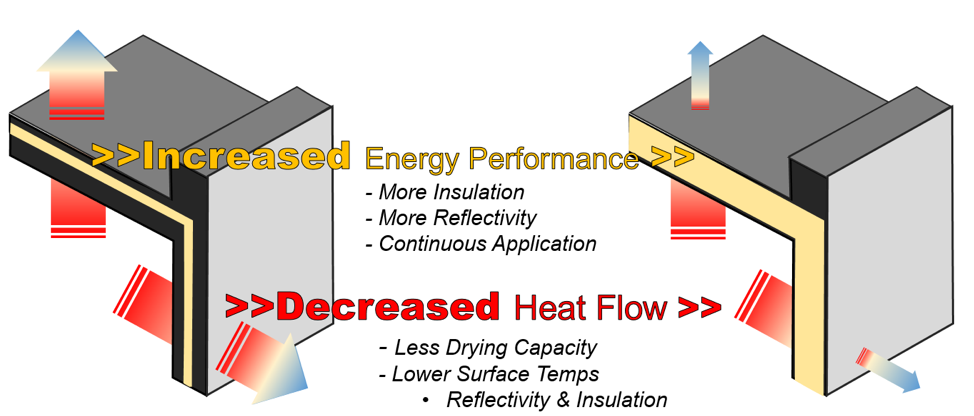 Energy efficiency improvements can lead to increased moisture risks in a building enclosure.
Image courtesy of GAF.
Operation Moisture Risk Elimination
In present day building codes, with their heightened emphasis on efficiency, it is ever more crucial to control moisture ingress into wall and roof assemblies. Importantly, control of moisture ingress from air leakage at assembly joints and vapor diffusion through materials can be achieved either using layer material specifically designed for the purpose, or through careful installation of, for example, the vapor thermal or air barrier control layer. All materials in a roof or wall assembly have some vapor retarding properties and the choice to include a specific vapor control layer should be made in consideration of the local climate, the building use, and the degree of assurance that vapor movement is retarded sufficiently.
The impacts from moisture intrusion are many. Certainly, leaks from the roof cause costly repairs, but they also can deteriorate the roof assembly and lessen its performance, including reducing R-values in the insulation, damaging interior finishes, and facilitating mold growth. Additionally, poorly controlled water ingress affects indoor air quality as mold growth in the roof assembly will find its way into the interior airspace of the building. In school and healthcare facilities, preserving IAQ and occupant health is paramount.
Bulk water
Bulk water, such as rain and snow, is kept out of buildings with roof membranes and wall cladding systems. Initially, roofs were created for this purpose. Keeping out bulk water consists of watertight detailing that is typical for any roof assembly. For facilities aiming at high levels of efficiency, including air tightness in conjunction with water tightness is a vital detail. Often, the roof membranes will serve as the air barrier, so proper detailing at penetrations and perimeters is vital. This includes tie-in with exterior wall assemblies to ensure a continuous air and water barrier.
Air-transported moisture
Air-transported moisture, as the name implies, is carried into or out of a building by air that infiltrates or passes through the building envelope. There are several types of air conveyance that can occur through the building envelope. Air infiltration is where exterior air enters the building through gaps in the exterior enclosure. Intrusion refers to the interior air that enters a roof or wall system but does not exit to the exterior. Interior air can be problematic where interior activities cause raised humidity levels in the air, one such example is in a gym, which are often located in both schools and hospitals. Large congregations of people exercising and exhaling increase moisture levels in the air; not to mention that shower facilities are usually adjacent to gyms, which also increases air moisture levels. Where uncontrolled moist air from gyms or showers enters into the roof assembly, condensation can form, often developing within the roof assembly. Condensation within the roofing assembly is not likely to evaporate, and this can lead to wet insulation, roofing components with lowered R-values, water accumulation in the roof deck, and the possibility of fostering mold.
Air exfiltration occurs where interior air exits from the building, also through gaps and inconsistencies in the building exterior. Exfiltration can lead to inefficient HVAC systems, where the building heating and cooling systems have to work harder to maintain interior temperatures, which ultimately leads to higher energy bills.
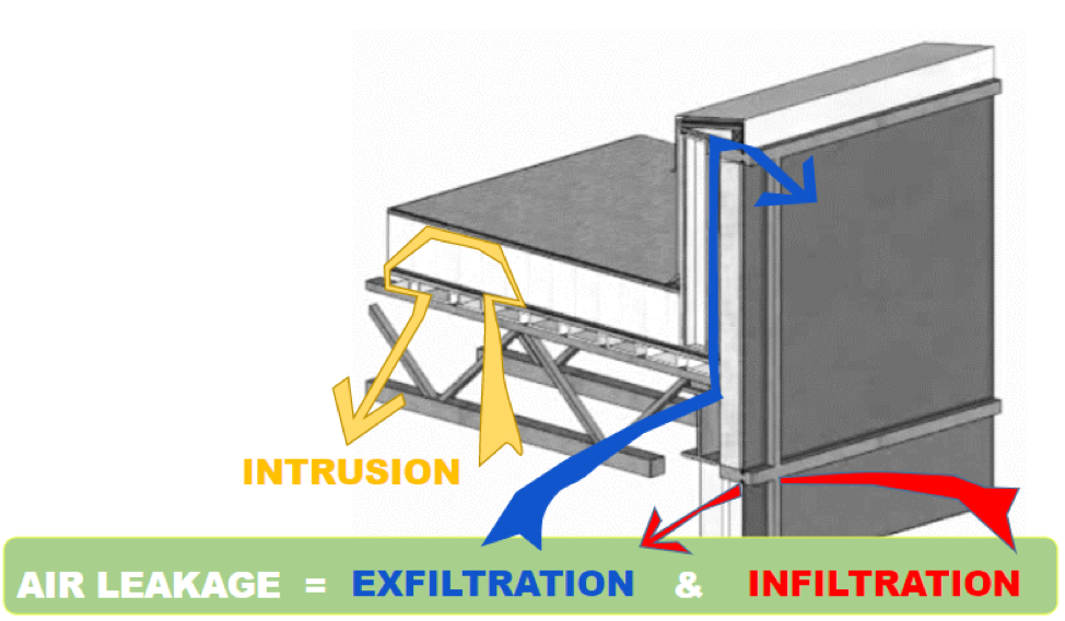 Air transported moisture.
Image courtesy of GAF.
Contrary to popular belief, air-transported moisture is much more critical to prevent than water vapor that enters a building by diffusion; condensation is likely to occur any time there is uncontrolled air movement. Controlling air leakage, and the associated moisture that air contains, can be of added difficulty when there are sources of moisture from the interior of the building, such as with gyms or shower facilities, which are often both located in schools and hospitals. Because of the amount of potential moisture carried by air, the code requires air barriers.
Vapor drive
Schools and hospital buildings are commonly maintained at set temperatures year-round. Depending on the climate zone, during summer months, the warm, moist outside air wants to move inward toward the cooler, drier interior. In the winter, this drive is reversed—the warm, conditioned interior air exerts pressure towards the cold exterior. The direction of the vapor drive experienced by the building dictates the best placement for vapor barriers, if recommended. Generally, the location of the vapor retarder should be located on the warm side. Oftentimes, the roof membrane acts as the vapor retarder and an additional vapor retarder is not required in the assembly. However, an analysis should be performed to determine if a dedicated vapor retarder is required and the most appropriate placement.
Managing Efficiency at the Roof: Air Barriers
Air moving through a building presents all kinds of hazards. First, uncontrolled airflow obstructs building conditioning. Building owners pay a lot for conditioned air. Air infiltration and exfiltration make up 25-40 percent of total heat loss in a cold climate. Air infiltration and exfiltration make up 10-15 percent of total heat gain in a hot climate. Losing one-third or more of conditioned air has a significant impact on the operational costs of a building. A 2005 study funded by the National Institute of Standards and Technology (NIST) simulated infiltration and exfiltration reductions in buildings and reported that, “Predicted potential annual heating and energy cost savings… ranged from 2-36 percent, with the largest savings occurring in heating-dominated climates…”
However, conditioned air loss is not the only concern. Uncontrolled air raises serious issues because of the moisture that air carries. Moisture in buildings can be damaging; moisture that has accumulated within the roof insulation will reduce the effective R-value. Saturated insulation has an R-value nearing zero, which is similar to having minimal insulation or no insulation at all. Dealing effectively with controlling airflow not only allows a building to save energy but also to mitigate moisture accumulation. Air barriers are systems of materials designed and constructed to control airflow between conditioned and unconditioned space, improving energy efficiency and comfort.
In 2012, the International Energy Conservation Code (IECC) published air barrier requirements, stating that a “Continuous air barrier shall be provided throughout the building envelope…” The purpose of an air barrier is straightforward: first, to minimize the loss of conditioned air from within a building, and second, to reduce energy loss and increase building energy efficiency.
It is important to distinguish that, the air barrier is often a system of materials that controls air leakage and convective heat flow through the building enclosure from the interior to the exterior. The air barrier is, critically, not one material, but instead is an integrated system of many different materials and components. As such, the connection of air barriers at interfaces between interfaces, such as the roof to exterior wall interface, is critical.
Roof air barrier code compliance
Designers should always consult local code to determine whether a dedicated air barrier is needed for a particular project. Under the widely adopted IECC 2018 and ASHRAE 90.1 2016, a building enclosure is required to function as an air barrier for all new construction except in climate zone 2b. Chapter 1 Scope and Administration, Section 101.4.3 references additions, alterations, renovations, or repairs. It reads as follows:
“Additions, alterations, renovations or repairs to an existing building, building system or portion thereof shall conform to the provisions of this code as they relate to new construction without requiring the unaltered portion(s) of the existing building or building system to comply with this code.”

 ASHRAE Climate Zone Map.
Properly installed roof membranes can be used as part of an air barrier system. Membranes can be considered as both the water and air control layer in a roof assembly. Roof membranes that are automatically considered by code to be suitable for use in an air barrier system are:
- Built-up roofing membrane.
- Modified bituminous roof membrane.
- Adhered single-ply roof membrane.
Single-ply membranes that are mechanically attached are also considered to be included, so long as the manufacturer can provide a data certificate confirming that the material has an air permeability of no greater than 0.004 cfm/ft2 (0.02 L/s · m2) under a pressure differential of 0.3 inches water gauge (75 Pa) when tested in accordance with ASTM E 2178. In practice, most manufacturers have this readily available on request. But note that the IECC states an important caveat, that materials shall be deemed to comply, provided that joints are sealed, and materials are installed as air barriers in accordance with the manufacturer’s instructions.
Roof membranes can be part of an air barrier system and their use will be considered code compliant only so long as they are correctly installed and tied into the wall air barrier layer.
There are two additional means of achieving compliance that are acceptable:
- First, assemblies of materials and components (sealants, tapes, etc.) that have an average air leakage not to exceed 0.04 cfm/ft2 under a pressure differential of 0.3 in H2O (1.57 psf) when tested in accordance with ASTM E2357, ASTM E1677, ASTM E1680, or ASTM E283. The following assemblies should meet these requirements:
- Concrete masonry walls that are fully grouted or painted to fill the pores
- Second, certification via whole building testing, where the air leakage rate of the completed building can be tested and confirmed to be ≤ 0.40 cfm/ft2 at a pressure differential of 0.3 inches water per ASTM E779, ASTM E3158, or equivalent method approved by a code official.
Ensuring air barrier effectiveness
Air barriers are required to prevent the loss of conditioned air from within a building. Using the concept of a complete roof assembly, it is important to have an air control layer that is complete and uninterrupted throughout the building enclosure. The materials that are part of that control layer should stop air movement and all tie together so that the potential for leaks is minimized. An air barrier’s effectiveness can be greatly reduced by openings and penetrations, even small ones. These openings can be caused by poor design, poor workmanship, damage by other trades, improper sealing and flashing, mechanical forces, aging, and other forms of degradation.
The National Research Council Canada collected research data that illustrates how even small openings can affect overall air leakage performance. As an illustration, only about 1/3 of a quart of water will diffuse through a continuous 4 feet by 8 feet sheet of gypsum during a one-month period, even though gypsum board has a very high permeance. However, if there is a 1-square-inch hole in this same sheet of gypsum, about 30 quarts of water can pass through the opening as a result of air leakage. Air leakage can cause more moisture-related problems than vapor diffusion.
It is the responsibility of the registered design professional to determine the need for an air barrier, verify an air barrier’s compatibility with other materials, clearly identify all air barrier components of the envelope, and provide details on joints, penetrations, and transition areas. The building designer needs to specify that the membrane not just overlap the wall air barrier, but also be flashed or sealed to it so that air cannot escape.
The simplest approach for the roof designer is to designate the roof membrane as the air barrier and carry it up and over a parapet wall, or over the edge if a parapet wall is absent. Once overlapping the wall, it must be terminated and sealed to the wall air barrier material so that air and moisture leaks are prevented.
While more complex to design and install, it may be prudent to have the air control layer extend through the base of a parapet to the wall. At that point, it must be terminated and correctly sealed to the wall air barrier. This approach minimizes airflow into the parapet and lowers the risk of condensation within the parapet.
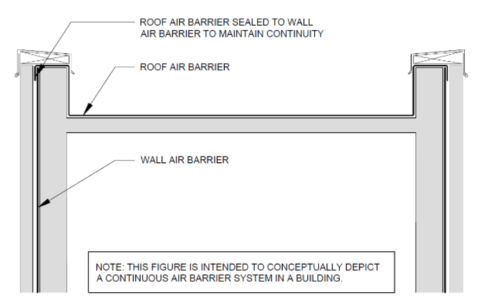 Simplified detail where the roof and wall air barriers are connected and continuous.
Image courtesy of GAF.
Managing Efficiency at the Roof: Vapor Retarders
Vapor retarders are commonly used in low-slope roof assemblies to perform two functions. The first is limiting airflow into the roof assembly. Minimizing the movement of air into the roof assembly, called air intrusion, reduces the movement of moisture-laden interior air into the building’s roof assembly, where condensation may be a risk. Second, vapor retarders are installed to reduce diffusion of moisture vapor through roof materials. Buildings with a higher risk for this type of diffusion are those structures where the building’s interior humidity conditions are expected to be relatively high, such as in natatoriums, or where the building is located in a cold climate. Additionally, vapor retarders can be used to help address moisture issues that can occur with structural concrete roof decks that contain a latent amount of moisture. Vapor retarders are therefore designed to resist diffusion of moisture through roofs and mitigate condensation potential. They can perform a vital role in protecting interior IAQ, efficiency, and structural integrity of the building components where condensation can wreak havoc.
Since vapor retarders are used to slow migration of water vapor, they make an excellent application for situations where controlling moisture mitigation and lowering condensation risks are important. At present, vapor retarders are not a code requirement. When properly detailed, however, all vapor retarders are considered air barriers. Conversely, not all air barriers are vapor retarders, leading to much confusion in the industry. Because vapor retarders block air, they can be used as both the vapor and air control layer. That said, selecting this approach should be used with care, since the barrier’s ultimate performance is highly dependent on careful design and installation. When a vapor retarder is located in an unintended place, or incorrectly placed, the vapor retarder can trap moisture in the roof system. A vapor barrier in the incorrect location can be equally problematic to not having one where once should have been installed. To be successful, the designated air and vapor control layers must be understood by everyone involved in the design, construction, and installation processes. Pre-construction meetings that review the control layers are essential, particularly for school and healthcare buildings, where errors leading to IAQ and health concerns cannot be tolerated.
 Vapor retarding properties of common building materials.
Vapor retarders material types
It is important to remember that all building materials have some vapor retarding properties, and the installation of a dedicated vapor retarder should be carefully considered. Most roofing membranes function as both air barriers and vapor retarders, and with correct application and detailing, they can meet the intent of the code. However, in low-slope roof assemblies there are several choices of possible materials for vapor retarders where a dedicated vapor retarder is required. Two categories of vapor retarders worth singling out are bituminous and non-bituminous. Bituminous-based vapor retarders are the most common and include self-adhering modified bitumen sheets and adhered smooth-surfaced APP or SBS-modified bitumen sheets. Additionally, there are built-up bituminous vapor retarders which are generally composed of one or two layers of asphalt felts or glass fiber mats applied with two or three applications of hot asphalt.
Non-bituminous-based vapor retarders include polyethylene film, plastic sheets, plastic laminates, kraft paper, kraft laminates and aluminum foil laminates. Some of these come with a self-adhering peel and stick backing and are generally self-sealing around fasteners. It is important to remember that vapor retarders, being installed lower down in a roof assembly, are frequently penetrated by fasteners from the insulation and membranes above, and installation of vapor retarders with self-sealing capabilities are advantageous to ensure that there is not air loss around penetrations.
There are non-bituminous types of vapor retarders that are installed loose-laid or adhered using a compatible adhesive to adhere the sheets to the roof deck or substrate. Black poly sheet, technically 6 mil polyethylene often referred to as Visqueen, is often used as a vapor retarder in residential crawl spaces. However, its use in roof systems is generally not recommended.
Vapor retarders in different climate zones
Whether or not to add a vapor retarder to a roof assembly design is somewhat complex and can be a judgment call based on the designer’s experience. The designer should take into account factors such as: what is the building’s continuous air barrier strategy? What is the building’s intended use? For example, interior swimming pools for physical education in schools and physical therapy in healthcare facilities will add large amounts of moisture to the internal air and significantly raise the risk of condensation within the building enclosure. As a less obvious example, cafeterias and laundry rooms in schools and hospitals can also have high humidity levels due to cooking and oftentimes large congregations of people. For schools and hospitals where these types of interior spaces are present, it may be prudent to consider a dedicated vapor retarder at the deck level.
It is good to factor in what the designer’s experience has been. While some regions experience sub-freezing winter temperatures, some designers may have not seen condensation occurring even when not using vapor retarders. Often a combination of the local climate, building use, and the roof assembly typically used can lead to a low condensation risk. From the discussion so far, it could appear that vapor retarders are only considered for buildings in the north, or in climates that have cold winters. However, there are scenarios in warm climates where vapor retarders should be used. Many schools and hospitals feature large footprints that have poured concrete floors. In some cases, the building is closed up before the poured concrete floor has completely dried. While this allows other trades to commence work quicker, it can lead to very high interior humidity levels. It is not unusual for designers and developers of such buildings to include a vapor retarder in the roof assembly design. Another example would be where, during winter construction, where gas-fired interior heaters are used inside the building. The moisture created from the heaters can accumulate within the roof assembly. Many months later, once the floors are dry and the heaters removed, the risk of condensation is minimal, but the presence of a vapor barrier at the roof deck level can prevent condensation and related damage during construction.
 Use of a vapor retarder is a judgment call, in some cases, for the designer. Using a vapor retarder in buildings with large building footprints, such as schools, can mitigate any potential moisture risks from drying concrete floors. Blue Valley School.
Photo courtesy of Shaw Roofing.
Taking Performance to the Top
Ultimately, roofing, as with any project, is not a one-size fits all. The design begins with determining the appropriate roofing assembly, including consideration to the interior activities and room types, roof deck type, insulation and cover board selection, completing the design down to the last termination and penetration detail, and installing the roof in accordance with the contract documents. Roof system design that aligns with or exceeds the expectations for energy efficiency and performance should be considered best practice for the project. Project specific requirements should be considered to determine the best assembly for the project. In addition, selections should be considered to impact the life cycle of the roof assembly, as material selection may decrease the overall life of the system and lead to increased replacement intervals. Replacement intervals are of particular importance for hospitals and schools where considerations such as time of year, VOC levels, and noise produced from roof replacements can be added challenges to the project.
Membrane selection
Selection of the roof membrane, the waterproofing layer that protects the building, is critical for success. The main consideration is the membrane performance, including color, thickness, and attachment. Improper selection of the membrane can result in loss of energy efficiency, water infiltration into the building, costly repairs, or even replacement. Single-ply membranes include EPDM, TPO, and PVC. The primary difference between the membranes is chemical composition, performance when exposed to chemicals at the roof surface, and treatment of the seams. Single-ply membranes are the most popular roofing membrane today due to their ease of installation and low cost, compared to asphalt-based materials. Single-ply membranes are, as their name implies, a single layer of membrane roof material and are produced in rolls. The chemical make-up of each of the membranes is different, and therefore, each of the membranes is preferable in different applications. Most single-ply membranes perform well when exposed to chemicals, however, particular chemical compatibility should be consulted depending on intended exposure. PVC and PVC Kee are exceptional when exposed to animal fats and grease, which is advantageous when located above cafeteria spaces. Another difference between the single-ply membranes is the treatment of the seams. TPO and PVC membranes are heat welded at the seams, which produces a monolithic roof membrane. TPO and PVC membranes are also more tolerant of ponded water, although it is a best practice to create taper in the roof assembly so that water evacuates the roof. EPDM seams are adhered, which creates a strong seam, but over time the adhesives may become brittle or deteriorate, leaving open seams in the roofing membrane, which may be problematic for long-term performance.
Modified bitumen is a modern-day built-up roof that consists of the same asphalt plies, but instead of building the plies on the roof, they are produced in rolls in a factory. Modified bitumen roofs offer the same durable protection of built-up, but with a faster and more consistent installation since the rolls are pre-manufactured offsite. Modified bitumen roofs consist of multiple layers including a base ply and a granulated cap sheet (called a two-ply system), where the cap sheet provides an excellent wearing surface. Modified bitumen roofs have a high tolerance for chemicals. While durable, over time, the granules in the cap sheet may become loose and shed exposing the asphalt below, which degrades over time with UV exposure and ponded water. The seams of modified bitumen rolls are often heat welded with a torch that melts the asphalt on the back of the rolls together, which forms a monolithic membrane. Due to the redundancy of the multiple layers in this type of system, modified bitumen roofing is the preferred of many school districts across the country.
Liquid applied roofs, not to be confused with liquid coatings, are roofs that consist of multiple coats of a liquid roofing membrane with an embedded reinforcement material between the layers. Liquid applied roofs are manufactured in many formulations including silicone and acrylic, and the selection depends on the underlayment as well as exposure to chemicals or other natural elements. They can be installed with sprayers or rollers and form a monolithic membrane across the roof surface. Liquid applied roofs are a common choice for school roof replacements due to the compressed replacement period that often occurs during summers. Similarly, liquid coatings, where a coating is installed on top of an existing roof system, are a common choice to extend the life of an existing roof system. Often, minimal preparatory work is required and since the original roof system is left in-place, liquid coatings are an excellent choice for hospitals and schools where minimal disruption is advantageous.
Hybrid assemblies, which is where two types of roof membranes are utilized, is a common choice for schools and hospitals due to the redundancy, ability to manage ponding water, and the cool reflective membrane to reduce energy consumption. One such assembly is where the base layers consist of asphaltic modified bitumen, and the cap layer is a reflective single-ply membrane such as TPO or PVC. A hybrid system such as this has increased durability, with effectively three plies or more of membrane. The addition of the reflective membrane will decrease roof surface temperatures and the building’s heat island effect, as well as can increase the resistance to certain chemicals if exposure is a concern. A hybrid assembly is also a common choice for recovery scenarios, where there is an existing modified bitumen roof and a single-ply membrane is installed on top. The addition of the single-ply membrane adds reflectivity and increases the service life of the roof assembly 15 years or more without an expensive and disruptive tear-off of the existing assembly. The addition of a single-ply membrane can be installed with low-VOC options that can have minimum odor and noise making activities that are beneficial in school and healthcare settings.
Membrane color
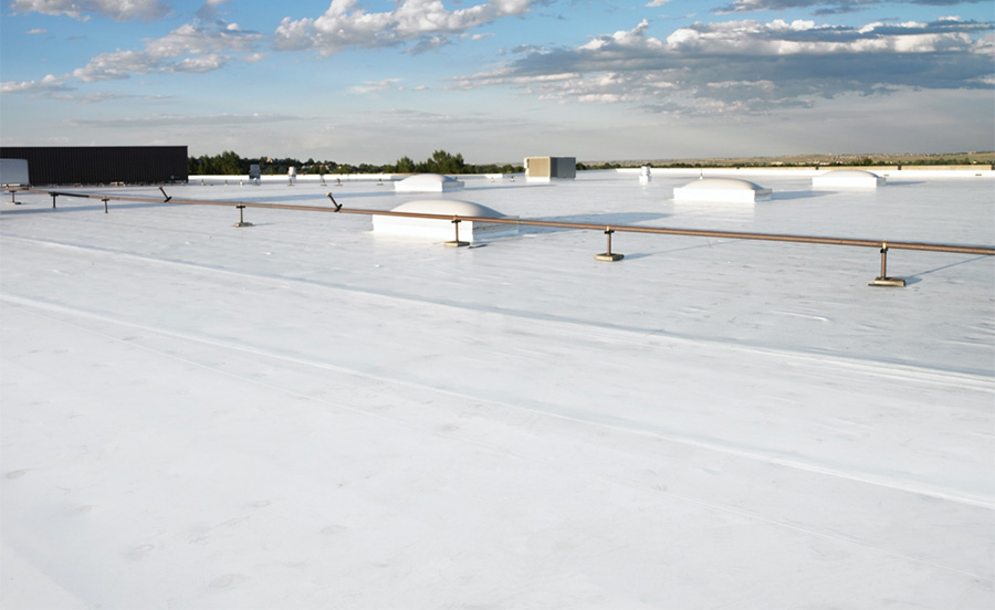 White or reflective roofing colors can have significantly lower surface temperatures, as much as 60 degrees Fahrenheit cooler, on a hot day.
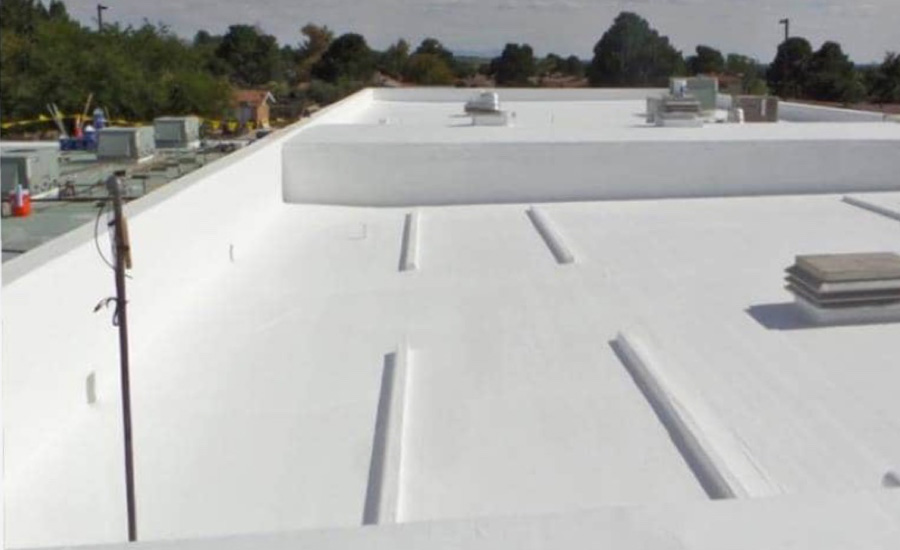
Photo courtesy of GAF.
Membrane selections can further be influenced by color, thickness, and attachment. For roof assemblies where the membrane is at the top of the system, the color can have a significant impact on the performance of the system and on the roof surface temperatures. Reflective roof membranes can lower the ambient roof temperature. EPDM membranes are traditionally dark in color, while liquid roofs, TPO and PVC are typically white or light in color. Modified bitumen roofs can have light colored granules which can increase reflectivity of a roof’s surface. Two roof surface temperatures, differing only by color, can vary by as much as 60 degrees Fahrenheit in the summer heat. Dark colored roofs can reach up to 150F, whereas white or reflective roofing colors can have significantly lower surface temperatures. Using a lighter colored roof can decrease the urban heat island effect in cities and may decrease the amount of heat that is able to radiate into a building’s interior. The more heat gain that a roof assembly absorbs, the warmer the interior temperature will be. In the summer, while the heat gain is offset by HVAC systems, the warmer an interior temperature is, the longer the systems have to run, which can increase energy use, and potentially raise energy bills.
According to a publication in the National Library of Medicine, “the patient is identified as being of prime importance for comfort standards in hospital ward areas.1 The steady-state condition preferred by patients was an air temperature of 71F.” Comfort regarding hospital accommodations can be closely tied with room temperature, and unsolicited heat gain or loss through the building enclosure, such as through the roof, can have a profound impact on overall patient satisfaction. Similarly, according to the Institute for Educational Sciences, classroom temperatures should be maintained between 68F and 75F during the winter months and between 73F and 79F during the summer months.”2 Inadequate building enclosures, including roof assemblies, where the temperatures cannot be properly maintained, can impede classroom learning. Selecting cool roofing assemblies, where solar heat gain can be controlled, can result in more than an efficient building assembly, they can impact student learning and patient satisfaction.
Reflective roof membranes, otherwise known as cool roofs, account for greater than 50 percent of roof surfaces installed on to low-slope commercial buildings each year, and an even greater percentage are installed in the southern half of the United States each year. Such reflective roofs have the potential for decreasing cooling energy consumption by lowering roof temperatures (Freund et al. 2006; Ennis and Desjarlais 2009; Gaffin et al. 2010; Graveline 2013). Research work strongly suggests that, regardless of location and local climate, selecting “cool roofing” will result in building space heating and cooling energy savings providing that buildings are heated with natural gas and cooled by electric air conditioning. While a building designer should model energy costs versus roof reflectivity on a case-by-case basis, some level of savings can be expected for reflective roof membranes. Even when aged reflectance and emittance values for cool roofs are factored in, energy savings remain at 85 percent of the initial installed values. This would suggest that energy cost savings achieved with cool roofs will remain, albeit slightly reduced, throughout the life expectancy of the roof.
Membrane thickness
The risk of installing a less robust system, such as that provided by a thinner single-ply membrane, could mean that the roof assembly would require replacement sooner than projected. Membrane thickness will increase resistance to puncture and foot traffic and extend the service life of the overall assembly. Note that hybrid assemblies, which combine two membrane types, most often modified bitumen and single-ply TPO, will increase system robustness and add additional protection from failure.
For single-ply membranes, adding additional membrane thickness can provide protection against punctures, which is especially important if the roof experiences foot traffic due to service and maintenance activities. According to a leading roof manufacturer, jumping from a 45 mil to an 80 mil single-ply membrane thickness significantly improves impact resistance by almost 80 percent. A thicker single-ply membrane also provides additional protection to both UV and high surface temperatures. For roofs using single-ply membranes, this is important, since a thicker overall membrane means more thickness over the scrim, or the reinforcing layer. It is this portion of the membrane that provides the weather resistant properties, including UV resistance. For modified bitumen membranes, two plies are considered typical, and the addition of a third-ply is generally not required, however, the addition of a single-ply membrane in a hybrid system will greatly increase the robustness and reflectivity of the system. Modified bitumen roofs, particularly those in a hybrid configuration, are generally considered more durable as total thickness may be 300 mils or more.
Liquid-applied roofs can be installed in varied thicknesses, with thicker systems being more durable over time. Liquid roofs are typically applied in several coats, with a fabric reinforcing layer in the middle to provide enhanced durability. Liquid roofs use liquid flashings at penetrations which is advantageous on roofs where there are a high number of or oddly shaped penetrations, such as roofs over science labs.
Membrane attachment
There are two broad categories of roof attachment: mechanically attached systems, via the use of fasteners, and adhered systems. The attachment method will vary depending on the membrane type, and project specific requirements such as energy efficiency, fume tolerance, and fire hazards.
Selection of attachment methods should be reviewed for ease of installation in the short-term and energy efficiency over the long-term. Energy efficiency from the roof assembly can be directly related to thermal bridging, which occurs when components allow heat transfer through the roof assembly. Loss of internal temperatures means that the mechanical equipment will have to work harder to maintain the desired set points. Thermal bridging has the potential to occur at gaps or discontinuities between materials, such as at fasteners in a mechanically attached system. Particularly where the fasteners penetrate the entire assembly from the membrane through the insulation and into the deck, the fasteners provide a direct thermal path from the exterior to the interior.
Mechanically attached single-ply systems are also subject to billowing in high wind events. Billowing, or fluttering, of a membrane is when wind causes a negative pressure by pulling interior air into the roof assembly creating uplift force on the roof assembly. Although this is an acceptable behavior of single-ply membranes, over time, it can cause stress and fatigue on the mechanical attachments and membrane. Interior air that is pulled into the roof assembly equates to energy loss, since often the temperature-controlled air may warm or cool based on the temperature of the membrane. Additionally, in healthcare settings where negative pressure rooms are required, uncontrolled air loss through fastener penetrations will likely impact the pressure in the room as well as the ability to effectively control contagions.
 Mechanically attached single-ply system, fasteners through the system act as thermal bridges.
Photo courtesy of GAF.
Systems that do not use fasteners, such as those which use adhesives, greatly reduce thermal bridging by eliminating the path from the interior of the roofing assembly to the exterior. Adhering also prevents billowing of the membrane, by mitigating the interior air that can be brought into the roof assembly.
Asphaltic based membranes use asphalt to adhere the roof assembly. Modified bitumen roofs can be installed by several different ways, including using a torch to melt the asphalt plies or by using a cold applied adhesive. The multiple asphalt plies form a robust roofing system that is not penetrable to air or the effects of billowing. Asphalt, and particularly hot (torch-applied) asphalt, can have strong fumes. On an occupied school or healthcare building, on a building in close proximity to other buildings, or on a building expansion, the use of asphalt may not be preferable since HVAC intakes may transport asphalt fumes into the building. Furthermore, some insurance companies and jurisdictions do not allow the use of torches on the roof due to the fire hazard of open flames.
Cold applied modified bitumen applications are an alternative that use an asphaltic based adhesive that is rolled onto the substrate prior to installation of the membrane. Cold applied applications offer the same modified bitumen wearing surface, but with fewer fumes than a traditional torch applied application. Modified bitumen roofs are excellent for mitigating air movement, as the multiple layers are impermeable to air, and therefore are not subject to billowing like mechanically fastened single-ply systems. Liquid applied roof membranes form a continuous membrane and are excellent for mitigating air movement, and are not subject to billowing, as they are installed directly on the insulation. However, the fumes of liquid applied membranes should be considered, as different formulations may exceed desirable VOC levels in occupied buildings.
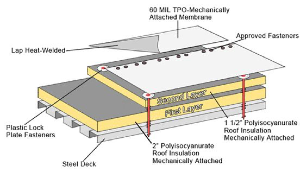
Single-ply membranes tolerate a wide variety of attachment methods and are able to be both adhered and mechanically attached. The types of adhesives can vary from melted asphalt (with fleece-backed membranes) to various types of commercial adhesives manufactured for specific single-ply membrane types. Although product specific, single-ply adhesives release fewer hazardous fumes during installation, in contrast to those emitted by asphalt-based products. These adhesives do not require heating or torching for application, and generally come in pails or canisters and can be installed with a roller or a spray attachment. Single-ply adhesives are generally less messy and can be quicker to install than traditional asphaltic-based products. Mechanical attachment of single-ply systems uses fasteners to install both the insulation layers and the membrane.
The fasteners must be continuous through each layer and into the structural roof deck for securement. The number of fasteners will depend on project specific requirements, but typically for a mechanically attached system, there is a minimum of six fasteners per 4-foot-by-8-foot insulation board, and additional fasteners for membrane attachment, which can lead to a substantial number of fasteners penetrating and creating thermal bridges within the roof assembly. It is important to note that most systems require mechanical attachment of the first layer of insulation, even if the specified system is to be adhered. However, by burying the fasteners within the system, and adding adhered layers of insulation and membrane on top of the mechanically attached insulation layer, the interior air loss and thermal bridging is significantly reduced. Location of fasteners in the insulation below a liquid applied membrane should be a consideration, as thermal bridging can still be a concern.
Insulation
Insulation is a critical part of any roofing assembly as it contributes to the overall energy efficiency of the building. According to a study completed by ICF International in 2021, roofing assemblies installed to current energy code requirements as compared to those installed prior to 2015, result in whole building energy savings of 2-11 percent.3 The study found that savings increase for colder climates and are highest for building types with large roof-to-floor ratios such as schools and hospitals. The effectiveness of roof insulation is determined by its R-value, which is a measure of thermal resistance. The higher the R-value, expressed per inch, the better the thermal performance of the insulation and its effectiveness at maintaining interior temperatures.
The most common roof insulation materials are polyiso, XPS, and EPS, each with different chemical compositions and material properties. Polyiso has the highest R-value at 5.7 per inch, followed by XPS with an R-value of 4.7 per inch and EPS with an R-value of 3.6 per inch. Higher R-value per inch means less material is required to achieve the desired insulating value. The thickness of the overall installation can have an impact on the overall design of the roof system. It is an industry standard for roof flashings to extend a minimum of 8-inches past the completed installation. Flashing heights are of particular importance at mechanical curbs and parapets. For a new construction installation, it is possible to raise the heights of the curbs and parapet walls to the desired height, however, in an existing building, this can be problematic.
Lightweight insulating concrete (LWIC) is an alternate type of insulation where EPS boards are encapsulated in a slurry coat of insulating concrete, then the membrane, and overburden would be placed on top of the LWIC. The R-value of the system and overall thickness are tailored to each unique project. LWIC can be advantageous for use with slope limitations because a desired slope can be achieved with the LWIC system. There are also no gaps within the installation, such as between standard insulation boards, and fasteners are not required to attach the LWIC, so there is limited thermal and air loss within the system.
While perhaps the most important criteria is insulating ability, mitigation of air infiltration is equally important. When warm outside air meets with cold inside air, condensation can form within the roof assembly, which can reduce the roof insulating value or cause microbial growth. Proper installation of the insulation is critical to mitigate heat and air flow. Where the membrane is the outermost layer, layers of rigid insulation are typically installed directly on the structural deck, and the membrane is subsequently installed on the insulation. The orientation of the boards during installation can play a significant role in energy efficiency in the assembly. The insulation should be installed in a minimum of two layers, and the joints in the top layer should be offset from the joints in the underlying layer. The edges of adjacent boards should be in contact to limit gaps between boards. Air and heat that is able to travel between gaps in the board results in energy loss. Gaps between boards can decrease insulating ability by allowing thermal loss, an increased condensation potential if air travels into the roof assembly. Air often brings moisture, which if allowed to condense within the insulation, can saturate the insulation boards. Wet insulation has an R-value of approximately zero, which is like having no insulation at all.
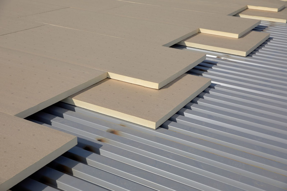 Staggered and offset insulation board joints.
Photo courtesy of GAF.
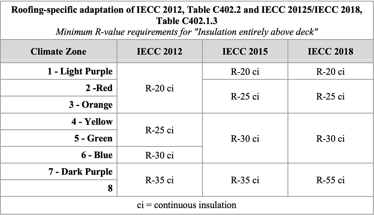
The Energy Code specifies minimum insulation R-values, as seen in the chart at Image 5. It is important to note that next to each required R-value, ‘ci’ is denoted, which is for continuous insulation. Similar to the continuous air barrier required by code, thermal insulation is required to be continuous; the insulation from the roof should continue, without interruption to the exterior wall insulation. Continuous insulation will assist in maintaining interior temperatures but will also eliminate voids in the building envelope where condensation is likely to occur.
Coverboards
Roof durability is dependent on the entire roof assembly, including the inclusion of a coverboard. Particularly rooftops with a large amount of mechanical equipment, such as hospital facilities, tend to have more trades and increased foot traffic on the roof. Schools with rooftop amenity space such as for classrooms or outdoor cafeteria seating have overburden systems, such as pavers, which add weight to the roof system, further increasing the need for a coverboard to protect the insulation. As with any roofing assembly, high traffic areas directly on roof membranes, such as those to service mechanical equipment, should be protected with walkway pads. Walkway pads, also sold in roll form, should be installed at roof access areas, such as hatches and around equipment, where they may be accessed for service or maintenance. Walkway pads protect against abrasion and wear, but do not add compressive strength to the overall roofing system. The addition of a high-compressive-strength cover board below the roof membrane will enhance system protection, including compressive strength. Cover boards can help provide added protection against penetration by objects, including tools dropped by service contractors, wind-borne debris, and hail. Increasing the thickness of the cover board will increase its penetration resistance.
Typical coverboard materials are high-density polyiso insulation (HD polyiso) and gypsum. High-density polyiso is a high-density version of the traditional polyiso insulation. A half-inch HD polyiso coverboard weighs 0.3 psf. The advantage of using HD polyiso is that it not only adds protection to the roof assembly, but it also adds an R-value of 2.5 per half-inch. Typical gypsum coverboards, with an equivalent half-inch board, weigh 2.76 psf and contribute an R-value of 0.5 per half-inch.
Roof Installation Considerations
While the roof assembly selection, including membrane and attachment method, is important for energy efficiency and performance goals of the building, ensuring a proper installation is critical to the long-term success of the roofing assembly. After the roof assembly has been decided, the roof details must be meticulously planned to include considerations for curbs, penetrations, flashings, and review of the control layers to include water, thermal, air, and vapor. The control layers must be continuous from the roof to the exterior walls. This prevents gaps in the system that can allow for water leaks, air leaks that may lead to condensation, or thermal breaks that may create locations of energy loss.
Additionally, the time of year and interior activities must be considered. For schools, the most common time for roof replacements is summer. This can create challenges as there are compressed schedules and weather delays cannot be accounted for at the end of the schedule. For most schools, the roof replacement must be complete by the time school is back in session. This does however, create several advantages, since there may not be occupants in the school, there may be less concern with fumes from the roofing components permeating into the building interior, as well as a higher tolerance for noise generating roofing related activities. Hospitals have their own challenges as in several occupant types in the hospital, there may be occupants 24 hours a day. This limits the ability for fumes and noise generating activities. But for both hospitals and schools, these limitations make the case for designing and installing a high-performance system during new construction. High-performance roof design will increase the time between roof replacement cycles as well as increase overall durability and resilience to weather events, foot traffic, and UV degradation which wreak havoc on roof systems. Additionally, high-performance roof systems will increase energy efficiency by mitigating uncontrolled air movement and thermal loss through roof components.
Summary
When designing an assembly for medical and student populations, it is critical to consider all elements of high-performance roof design. Air control becomes essential to reduce transmission rates, facilitates greater control of interior temperatures and humidity levels, as well as manage condensation risk and the potential for mold growth, which can negatively impact indoor air quality. These details will impact the performance of the assembly and contribute to an energy efficient building and extend the useful life of the roof. Design of high-performance roofing assemblies, from the selection of the membrane, coverboard, insulation, and overall attachment method will not only impact the overall lifespan and durability of the roof assembly, but it will impact the performance, including energy efficiency of the system. High performance roof design will extend the life of the roof components, which will increase the time between replacement intervals. Construction generated odors and noise can be managed through intentional design to address the needs of students and recovering patients. Through intentional design and construction, a holistic approach can be implemented on medical and student-based campuses to protect the health, safety, and welfare of a vulnerable population.
Complete the quiz and receive a certificate of completion
Earn: 1 AIA LU/HSW; 1 IIBEC CEH; 0.1 IACET CEU
End Notes
1. Smith RM, Rae A. “Thermal comfort of patients in hospital ward areas.” J Hyg (Lond). 1977 Feb;78(1):17-26. doi: 10.1017/s0022172400055881. PMID: 264497; PMCID: PMC2129728.
2. “Optimal classroom temperature to support learning.” Regional Educational Laboratory Program. November 2018.
3. 179D Commercial Building Energy Efficiency Tax Deduction.
Looking for a reprint of this article?
From high-res PDFs to custom plaques, order your copy today!
.webp?height=740&t=1767036885&width=auto "Header - BE 1170x658 (002).png")

.webp?height=740&t=1755781744&width=auto "KEE(2).png")