Sponsored by GAF
CEU: Roofs for Cold Storage Buildings
Building science and construction come together in cold storage buildings

LEARNING OBJECTIVES
After reading this article, you should be able to:
- Identify the risks associated with common cold storage design and installation practices.
- Review the importance of air-, vapor- and thermal-control-layer continuity.
- Assess typical cold storage details to evaluate control-layer continuity.
- Discuss construction sequencing and winter construction challenges.
Complete the quiz and receive a certificate of completion
EARN: 1 AIA LU/HSW; 1.5 GBCI CE HOUR; 0.1 IACET CEU; 1 IIBEC CEH // AIA COURSE #BE2020B
Introduction
Cold storage buildings are often thought of as a typical building turned inside out. These buildings are designed to keep heat out instead of keeping heat in during cold weather. But is it that simple? This course will review the importance of the unique construction assemblies required for cold storage buildings, the primary control layers and their continuity, and how we need to think about the use of the primary control layers to reduce the risk of condensation in this inside-out scenario.
The intent of this course is to provide information that promotes long-term performance and durability, as well as the long-term energy efficiency of roofs and the overall building enclosures that are part of cold storage buildings. Much of this course focuses on transitions from roofs to walls and rooftop penetrations.
Let’s Start with a Definition
A “cold storage building” is a building or a portion of a building or structure designed to promote the extended shelf life of perishable products or commodities. It’s important to recognize that there are varying levels of cold storage, such as coolers, chill coolers, holding freezers, and blast freezers. Coolers range from approximately 32–55 degrees Fahrenheit (0–13 degrees Celsius), while blast freezers can have interior temperatures from minus 20–50 degrees Fahrenheit (minus 29–46 degrees Celsius).1 The biggest difference from a roofing perspective is the amount of insulation for the varying levels of cold storage applications.
Note: For the purposes of this article, all of these varying degrees of cold storage and freezer facilities will collectively be referred to as “cold storage buildings.”
What Is the Risk?
The primary concern for proper roof design of cold storage buildings is the significant vapor drive that occurs predominantly from the relatively warmer exterior toward the colder interior. That directly leads to two critical aspects of the roof design: 1) proper placement of a vapor retarder to manage the vapor drive, and 2) proper detailing to prevent air infiltration or exfiltration at enclosure transitions and penetrations. Additionally, the reduction or elimination of thermal bridges (i.e., locations such as fasteners where heat flow is increased in comparison to the insulation) is important because of the critical need for a highly effective thermal boundary—which, of course, keeps the items within the cold storage building at the proper temperature all while using the least amount of energy.
Examples of Risk
There are many different examples that indicate there is some type of an air/moisture issue at roof penetrations and/or the roof-to-wall intersection of cold storage buildings. Many of these are substantial issues serious enough to call them enclosure failures. Typical scenarios that constitute failures include snowflakes (literally frozen water floating down in the interior) and icicles at perimeters and penetrations. These types of issues manifest themselves on the interior and are not only energy-efficiency issues but also potential safety issues for occupants.
Ice can form within the joints of roof insulation and within the insulation itself. Gaps between insulation boards can fill with water vapor and become ice (see Photo 1.) The R-value of the insulation is effectively zero when the boards and board joints are frozen. Insulation boards can freeze and heave up. Remember: Water expands when it freezes. Non- or under-insulated expansion joints are probable locations for condensation to occur, possibly resulting in ice development due to excessive and continued formation of condensation. Roof details that do not include an air barrier are also potential locations for condensation to occur. A final example, the joints between insulated metal wall panels (IMWPs) used as the wall (and parapet) are susceptible to air movement and freezing. These examples represent a loss of performance, durability, and energy efficiency, as well as the potential of premature failure and the need to replace a roof system on a cold storage building.
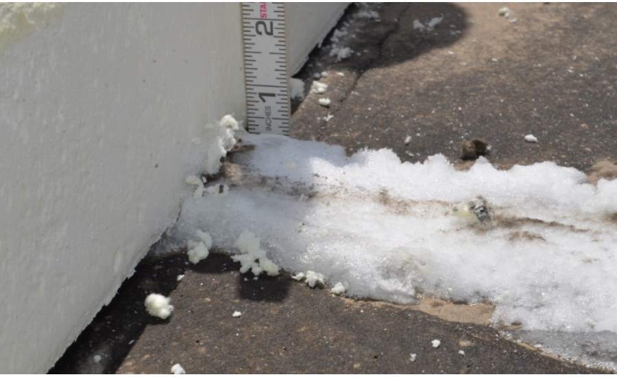
PHOTO 1: Shown is ice buildup between rigid insulation boards in the roof of a cold storage building. Photo courtesy of Hutchinson Design Group Ltd.
Energy Efficiency and Air Leakage
There is a direct relationship between energy efficiency and air leakage. Therefore, a discussion about cold storage buildings would not be complete without some background about energy efficiency and air leakage. Energy standards have improved over the past 20 years, and these improvements have increased energy efficiency of buildings overall. Roofs can be a large portion of the building enclosure for one- and two-story buildings. It’s important to manage the energy use of buildings, especially cold storage buildings that are users of large amounts of electricity.
Managing energy use starts with the design of the building enclosure. The building enclosure encompasses all six sides of a building, but oftentimes the interior of a cold storage building will have multiple interior space conditions, such as a loading dock or the office portion of the building. A cold storage unit within a larger storage facility with open truck docks, office space, and semi-conditioned storage can create a network of separate interior conditions that can lead to difficult enclosure tie-ins and connections between spaces with varying working environments.
The keys to managing energy include properly insulating the building enclosure and interior separations and reducing air leakage for a cold storage building. Every roof penetration is a potential air-leakage location and should include air-sealing components. Because a roof can be such a large part of the building enclosure, it plays a large role in the overall energy efficiency of a building. In fact, energy efficiency has been shown to be improved in all climate zones when air barriers are used.2
For air to move into or through the building enclosure, two things are needed. First, there needs to be a pressure differential. This pressure differential can come from wind, stack effect, or mechanical ventilation. Second, airflow needs a pathway into or through the building enclosure. Architects and roof designers—through the design of proper construction details—can significantly affect the long-term control of airflow into and through the building enclosure. It’s prudent to specify the use of air barriers that are constructible, compatible and properly located to reduce or eliminate paths for airflow.
There are three types of air movement that need to be considered when designing the building enclosure: infiltration, exfiltration and intrusion. Figure 1 shows each graphically. Essentially, infiltration and exfiltration are types of air movement through the entire building enclosure. Air infiltration is air from the exterior that enters the building through the enclosure, and air exfiltration is air from the interior that exits the building across the building enclosure. Air moving through the enclosure (both infiltration and exfiltration) is also called air leakage. Intrusion is air that enters a roof or wall system but does not exit to the exterior; an air barrier prevents the passage of air through the entire building enclosure.
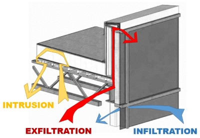
FIGURE 1: Shown is air intrusion into a roof system and air exfiltration and infiltration across the building enclosure. Graphic courtesy of GAF
While this article is focused on the moisture that air carries, it’s important to point out that air also carries heat and contaminants. The unwanted loss or gain of heat energy via airflow increases the need (and expense) for heating and cooling equipment to operate and maintain a comfort level. Therefore, appreciably reducing the unwanted loss or increase of heat energy by incorporating air barriers reduces the burden on heating and cooling equipment. Also, air contains particulates, some of which can be contaminants for users and occupants of a building. For example, an idling delivery truck’s exhaust can be brought into a building when the air leakage is from the exterior to the interior.
The Building Science Perspective
Heat and moisture flow through the walls and roof of a cold storage building is quite different than a conventional building type, such as an office building. The second law of thermodynamics helps explain how heat, air and moisture move (see Figure 2), and a cold storage building is an excellent example of the need to understand these fundamentals. These principles include:
● Heat flow is from warm to cold.
● Moisture flow is from warm to cold.
● Moisture flow is from more to less (wet to dry).
● Air flows from higher pressure to lower pressure.
● Gravity acts down.
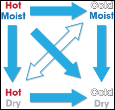
FIGURE 2: Shown is a graphic example of the second law of thermodynamics as it relates to heat and moisture. Graphic courtesy of GAF.
Importantly, heat, moisture and pressure always want to equalize across a boundary. For a cold storage building, this boundary is the “six sides” of the building enclosure—the roof, walls and floor.
Air Leakage and Vapor Diffusion Principles
Air-transported moisture is a more significant issue than vapor drive because of the relative amount of moisture transported by each process.
Research data illustrates how even small openings can affect overall air-leakage performance. For example, only about one-third of a quart of water will diffuse through a continuous 4-foot x 8-foot sheet of gypsum during a one-month period, even though gypsum board has a very high perm rating. However, if there is a 1-square-inch hole in this same sheet of gypsum, about 30 quarts of water can pass through the opening as a result of air leakage.3 This is essentially 100 times more moisture gain due to air movement through a small hole versus the moisture gain from diffusion. This relationship is illustrated in Figure 3. This example illustrates that air leakage can cause more moisture-related problems than vapor diffusion. This is why the International Energy Conservation Code has mandated air barriers for new construction since 2012.
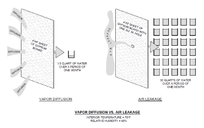
FIGURE 3: Shown is the difference in the amount of moisture that moves via diffusion and via airflow. Graphic courtesy of GAF.
Accordingly, it’s critical that a vapor-retarder system be continuous when used in cold storage buildings so it also serves as an air barrier.4 Most commonly, the roof membrane serves as the vapor retarder/air barrier. Penetrations and the roof-to-wall interfaces should be sealed to prevent air leakage (see Photo 2) because discontinuity will allow air to flow through the discontinuity, which can then lead to condensation problems.
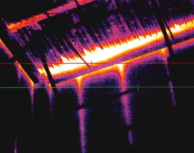
PHOTO 2: Shown is a screen capture of an infrared image looking up at the underside of a metal roof deck where the roof meets the walls. Graphic courtesy of GAF
For cold storage buildings, much of this discussion manifests itself at the roof-to-wall intersection around the entire perimeter of the building. Consistent detailing of the control layers around the entire building enclosure is needed for long-term performance and proper installation. However, designers must consider that some deck types (e.g., steel decks) have different profiles/terminations that need to interact with the wall. Steel decks have open flutes that abut/meet the wall on two sides, while the other two sides, due to the profile of the steel deck, abut with a solid profile. Each requires different emphasis during construction to prevent unwanted airflow within the deck itself. The Details section of this article provides more information.
Concepts for the Design of Cold Storage Buildings
A cold storage building should have building enclosure with these attributes:
● Adequate amounts of insulation and an appropriate attachment method to maintain interior temperature and minimize thermal loss.
● Compensation for thermal expansion and contraction.
● Control of air- and water-vapor movement.
There are three conceptual methods for the design of a cold storage building:
● Exterior envelope system
● Interior envelope system
● Building-in-a-building system
Exterior Envelope System Method
This method entails a vapor-retarder system located on the exterior side of the building’s structural system. The vapor-retarder system “encapsulates” the building by being located on the outside of the exterior walls’ insulation layer, under the floor and over the roof’s insulation layer.
Interior Envelope System Method
This method entails a vapor-retarder system located on the interior side of the structural system. In this scenario, the vapor-retarder system is located under the roof deck, inside the exterior walls and above the floor.
Building in a Building
This method entails constructing a cold storage structure within a building’s enclosure. The insulation and vapor-retarder system then may be applied to the outside of the inner structure’s envelope. See Figure 4 for a conceptual depiction of this method. With this solution, the outer building envelope structure provides a more constant temperature around the cold storage structure and eliminates exposure to the sun’s heat. It should be noted that the roof system on the outer building is not to be considered a “roof over a cold storage building” because the interior space beneath it’s normally conditioned.
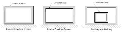
FIGURE 4: Shown are three conceptual methods for the design of a cold storage building. Graphic courtesy of GAF
The most common way to achieve these objectives is to use the exterior envelope system (EES). The EES method uses a vapor retarder that is located on the exterior side of the building’s structural system. More specifically, the vapor retarder encapsulates the building and is located over the roof’s insulation layer, on the outside of the exterior wall’s insulation layer and under the floor. This article focuses on the EES method.
Cold Storage Design Considerations [section head]
The design and construction of cold storage buildings requires attention to the following considerations:
• Building location
• Design values
• Roof insulation
• Thermal shorts/thermal bridging
• Expansion and contraction
• Air leakage and water-vapor movement
• Vapor-retarder perm ratings
Building Location
In warm climates (e.g., Dallas), the prevailing vapor-drive direction is inward, and therefore, the most effective location for a vapor retarder/air barrier is on the outside of the roof insulation. In most cases, the roof membrane will be the vapor retarder.
In moderate climates (e.g., Nashville and Kansas City), the vapor drive may be in either direction, and the location of the vapor retarder/air barrier depends on the predominant direction of the vapor drive. However, because there is generally more total moisture in the air during the summer months (versus winter months), the predominant vapor drive is into the building. Again, the roof membrane will be the vapor retarder.
In cold climates (e.g., Buffalo), the vapor drive will be reversed when the outside temperature is colder than the interior temperature, but there is less concern with condensation issues because cold air has a relatively small amount of moisture; and because the temperatures are often similar, vapor drive is less significant.
Design Values
If a roof system designer chooses to perform a dew-point or hygrothermal analysis to confirm the placement of the vapor retarder/air barrier, the following is needed:
• Interior dry bulb temperature
• Interior relative humidity
• Exterior dry bulb temperature
These values are theoretical constant values based upon design assumptions for a single point in time, yet in reality, these change from day to day and season to season.
Roof Insulation
Insulation plays a critical role in the building enclosure performance of a cold storage building. To minimize the potential for interior condensation, appropriate amounts of insulation should be used so the interior surfaces of the building enclosure are kept above the dew point. Insulation type and R-value selection are affected by numerous factors, such as cost, desired energy efficiency, suitable material properties, interior design temperatures and climatic conditions. Figure 5 offers suggestions for minimum R-values for roof insulation in cold storage buildings.5
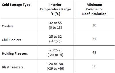
FIGURE 5: Shown are the suggested minimum R-values for roof insulation used in cold storage buildings. Graphic courtesy of “Energy Modeling Guideline for Cold Storage and Refrigerated Warehouse Facilities” by the International Association for Cold Storage Construction and the International Association of Refrigerated Warehouses.
The type of insulation used should be suitable and compatible for use in a cold storage building. A commonly used insulation type is polyisocyanurate insulation (polyiso), which has the highest R-value per inch compared to other insulation types used in the roofing industry.
Thermal Shorts/Thermal Bridging
Designers should pay close attention to thermal shorts (e.g., gaps between boards) and thermal bridging (e.g., metal fasteners and plates) when designing roofing systems over cold storage buildings. To reduce the effects of thermal shorts, roof insulation should be installed in at least two layers with offset joints—vertically and horizontally—to minimize air leakage and movement. Gaps between insulation boards should be filled.
To reduce the effects of thermal bridging (e.g., loss of R-value, condensation potential), the roof membrane and upper layer(s) of rigid board insulation should be adhered. Mechanical fasteners should be avoided as the securement method for the roof membrane and upper layer(s) of rigid board insulation. When the substrate is a nailable deck, such as steel or wood, the first layer of insulation (i.e., the layer in direct contact with the roof deck) may be mechanically attached. Subsequent layers should be installed with adhesives to reduce or eliminate thermal bridges. When the substrate is concrete, adhesives or fasteners can be used to install the first layer of insulation, with subsequent layers adhesively attached.6
Expansion and Contraction
Accommodation should be made for thermal movement in cold storage buildings. Building movement may lead to tearing of or damage to a vapor retarder/air barrier or the roofing system. Pipes in roofs and walls may move due to thermal expansion and contraction as well as vibration, so it’s important to select pipe penetration flashings that can accommodate movement, such as pre-manufactured flashing boots.
Air Leakage and Water Vapor Management
Cold storage buildings are maintained at temperatures that are most often much lower than the exterior temperature. In this case, the warm, moist outside air wants to move to the interior of the cold storage building. This is especially the case in southern climates and is generally true for most geographic locations in the United States for most months of the year. Therefore, the direction of the vapor drive is predominantly from the exterior to the interior. This means the roofing membrane will act as the vapor retarder and air barrier, which keeps vapor and air from moving into the roof system and creating condensation problems.
There may be times during the year in colder climates where the warmest cold storage buildings—a cooler with a temperature range from 32–55 degrees Fahrenheit (0–13 degrees Celsius)—may experience a vapor drive from the interior to the exterior because it’s colder outside than the interior. However, this is not likely problematic for two reasons. First, the amount of absolute humidity inside a cold storage unit is low because of its low temperature and relative humidity.7 There just isn’t a lot of moisture relative to the interior of, say, an office building. Second, because vapor drive also relates to pressure differences, a cold, dry space (the interior of a cold storage unit) does not exert a pressure significantly greater than the cold, dry air of the exterior in a winter climate. Ultimately, a cold storage unit in a northerly climate should not experience a moisture gain within the roof system. And any moisture gained during the winter will be driven back into the cold storage portion during the warmer summer months.
Problems occur when there are paths for air and water-vapor movement within the building enclosure. It’s imperative that the vapor retarder and roof system be continuous, tied to the wall air barrier and completely sealed at:
• laps and seams.
• roof penetrations (i.e., pipes, structural members, mechanical curbs, roof hatches, etc.).
• roof-to-wall interface/intersections.
Special attention should be paid to steel roof decks which are used in many cold storage buildings because of their ability to allow significant lateral movement of air within the deck flutes. Limiting the number of penetrations through the roof assembly is also prudent. If a separate vapor retarder/air barrier is used at or just above the roof deck, avoid attaching the roof system through the vapor retarder with mechanical fasteners for cold storage buildings. This helps maintain the vapor retarder’s integrity.
Vapor-Retarder Perm Ratings
Vapor retarders are typically membranes with relatively low permeance values, but not all vapor retarders are equal. There are three classes of vapor-retarder materials, as shown in Figure 6.
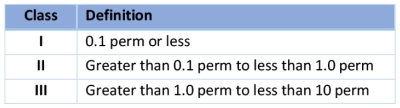
FIGURE 6: Shown are three classes of vapor retarders; each class has different perm ratings. Graphic courtesy of GAF
Most roof membranes are Class I vapor retarders. Perm ratings for single-ply membranes range from 0.03–0.06 perms. An example of a Class II vapor retarder is asphalt felts, which have perm ratings ranging from 0.3–0.8 perms. Examples of Class III vapor retarders are latex or acrylic paint. Class I vapor retarders should be used on the outer surfaces of cold storage buildings that are designed and built using the EES method.8 If a second vapor retarder is used at the deck level (to prevent construction moisture from infiltrating the roof system), a Class III vapor retarder should be used to allow some downward drying. It’s important to note that these are material ratings; the entire vapor and air management system needs to be designed and installed correctly for proper functionality.
Details
All of these concepts—moisture and vapor drive, thermal control—come together at the intersections of systems (e.g., roofs and walls) and penetrations, and these are the locations that should have construction details developed for use during the bid phase and certainly during the construction phase.
Thermal efficiency considerations include multilayer insulation, where fasteners and adhesives are located within the system. Designs with the first layer attached and the upper layers adhered is shown to be most effective.9 Because air leakage is an important part of energy efficiency, consider the direction of the vapor and air drive; when placing the air barrier on the exterior, it’s important to locate the air seals toward the exterior so they are positioned to be the first line of protection against air infiltration.
Consider expansion and contraction as well as differential movement. Cold storage buildings can experience a larger temperature differential from interior to exterior given the low interior temperatures, relative to typical office buildings that have interior temperatures of approximately 70 degrees Fahrenheit.
Using insulation with high R-value per inch reduces the total insulation thickness. This may also reduce the length of fasteners, depending on attachment design. One way to eliminate the need for tapered insulation is to slope the structural deck.
Considering the location and constructability of the connections and tie-ins for the air-barrier details is long-term risk management. The roof membrane is the vapor-control layer and the air-control layer for the primary vapor and air drive for cold storage buildings. Of the two, the air-control layer is more critical for long-term success.
Special attention should be paid to steel roof decks, which are used in a large number of cold storage buildings, because they pose a detailing issue regarding air control. It’s challenging to air-seal steel roof decks at walls and penetrations. Deck flutes can serve as “conduits” or pathways through which air and air-transported moisture can flow. To minimize airflow, flutes can be filled with closed-cell spray polyurethane foam (SPF) at walls and penetration locations. Figure 7 is an example of a roof-to-wall construction detail showing SPF used to create a continuous air barrier from the wall to the roof.
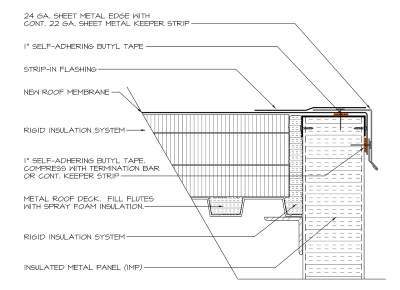
FIGURE 7: Shown is the use of spray polyurethane foam as the tie-in from the roof air barrier to the wall air barrier. Detail courtesy of Matt Dupuis, SRI.
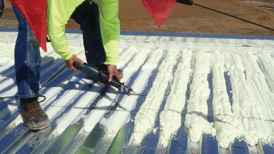
PHOTO 3: Shown is the installation of spray polyurethane foam in the flutes of a steel deck. Photo courtesy of Matt Dupuis, SRI.
It’s important to recognize that a steel deck meets a wall with two different profiles because its profile is not the same in each direction. The foam may need to extend 1–4 feet along the flutes when the flutes are perpendicular to the wall to prevent the communication of air from the roof to the wall, which can result in interior icicles. When flutes are parallel to the wall, perhaps only the first flute or two needs to be filled. Two construction details are needed to ensure that air is properly controlled at the roof-to-wall intersection.
Wood blocking is often used at roof edges to create a robust edge for securement of the edge metal. However, the thermal resistance (per inch) of wood blocking is low relative to the primary insulation used in the roof and walls, certainly for IMWPs. The wood blocking is, relatively speaking, a thermal discontinuity. Proper air sealing is important at areas of reduced R-value to reduce the potential for air-transported moisture to reach locations where it will condense. The use of non-curing butyl tape between the top of a wall panel and the underside of the wood blocking, in conjunction with closed-cell spray foam (ccSPF) in the flutes and between the stack of wood blocking and the ends of the rigid insulation creates a roof-to-wall element that effectively continues the air barrier from the roof to the wall. Figure 8 is a good example of this condition.
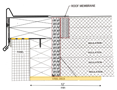
FIGURE 8: Shown is wood blocking used as a robust edge condition to secure the edge metal. Proper air sealing is important at areas of reduced R-value. Graphic courtesy of GAF.
Raised roof edges are often the result of using balloon framing construction methods, such as IMWPs extending vertically past the roof deck, the insulation, and membrane flashing. See Figure 9. A raised roof edge is commonly protected by a metal coping. The flashing membrane is extended up, over and down the face of the raised roof edge. In this scenario, the outer face of the IMWP is considered to be the air barrier.
Air seals are needed at the metal deck where it meets the wall and support angle, and air seals are needed between the face of the IMWP and the edge of the insulation boards. This is a critical location for air leaks and condensation potential. Leveraging SPF materials provides a constructible detail. Also, air sealing is needed between the membrane and each face of the IMWP when installed as a raised roof edge. In this scenario, air-leakage control is necessary on both surfaces of the IMWP. This brings two considerations into play for air sealing.
First, the joints between the IMWPs need to be air sealed. Left unsealed, the joints are a direct path from the exterior to the roof deck and roof insulation. This is an important location to air seal properly. It’s not good practice to only rely on the outer (exterior) seal to be the air barrier. Importantly, the vertical joint between IMWPs is a path for air leakage and intrusion. Breaches to any portion of the exterior seal will allow air to move between the panels and within the vertical joint, which can easily reach the raised roof edge. Therefore, the interface between the roof and IMWP must be sealed on the interior side as well. An air seal on the outer and inner surfaces—a double air seal—is an excellent way to block air exfiltration and infiltration. If these joints are not air sealed, they can allow airflow and the moisture and heat it holds to bypass the air-control layer and enter the building. These same considerations are true for precast concrete wall panels that are installed outboard of the roof deck and extend vertically past the completed roof system.
Second, when using a corrugated IMWP, the corrugations are difficult to air seal. Specifying the use of flute plugs that “fill in” the corrugations allows for a successful air seal between the surfaces of the metal wall panel and the air-barrier membrane (e.g, the roof membrane). During installation of the roof membrane, ensuring the roof membrane extends far enough over the perimeter edge to allow for proper termination and continuity is important. And let’s not forget the basics: Staggering and offsetting the board joints between the multiple layers of insulation provides for some air control.
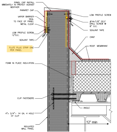
FIGURE 9: Shown is a raised roof edge with air seals between roof and wall, as well as flute plugs where the membrane wraps over and down the exterior of the IMWP. Graphic adapted from Metl-Span.
For these and other constructability issues, onsite mockups can be helpful to work out detail specifics and workmanship issues prior to final construction. The construction and testing of mockups should be in the construction documents and specified so there are no surprises.
There often are different conditioned spaces within a single facility. Offices and loading docks are often part of a cold storage building. These spaces should be separated thermally and should not allow air movement from space to space. That means ensuring there are air seals and continuous insulation at the intersection of outer walls and the roof, and given the different interior environments, also at the intersection of inner walls and the roof.
To accomplish this separation of conditioned spaces, a membrane strip can be turned down through the insulation layer and adhered to the deck. This type of detail prevents lateral airflow from the roof above a warm office space into the roof above a colder cooler or freezer portion of the building. For steel decks, flutes should be filled to prevent lateral airflow, especially when the flutes of the metal deck are perpendicular to the separating wall. For solid decks, an air seal (e.g., butyl tape) should be used to seal the membrane to the deck. Photo 4 and Figure 10 show this detail as built and as designed.
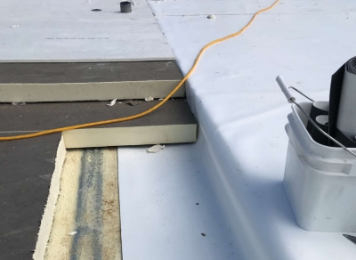
PHOTO 4: Shown is a roof membrane through insulation and adhered to roof deck to prevent lateral air movement. Photo courtesy of Matt Dupuis, SRI.
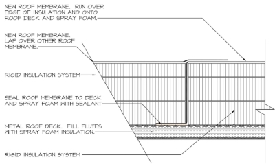
FIGURE 10: Shown is a roof membrane through insulation and adhered to roof deck to prevent lateral air movement. Detail courtesy of Matt Dupuis, SRI.
If the interior wall extends higher than the roof deck (essentially separating two roof areas), not only does air infiltration need to be minimized or eliminated, but there is also the potential for thermal bridging at this location. Figure 11 shows this configuration. The top layer of insulation and the membrane should be adhered to reduce the thermal bridging potential of the fasteners and plates. An intentional gap between the IMWP and the roof insulation allows for the use of ccSPF to prevent lateral air movement. Again, where the metal deck flutes are perpendicular to the separating wall, filling the flutes with spray foam helps prevent lateral air movement.
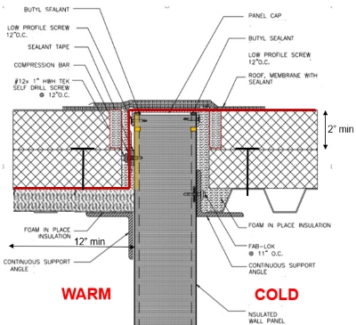
FIGURE 11: Shown is a separating wall between two differently conditioned spaces. Graphic adapted from Metl-Span.
Another way to help reduce thermal bridging where an IMWP extends to the underside of the roof membrane is to make a saw cut on both sides of the metal panel. This literally disrupts the thermal bridging of the metal skin of the IMWP. Placement of the cut matters; if it’s too far down the panel, structural issues could arise. The specific IMWP manufacturers can provide guidance on the best location and depth of the cuts to limit thermal bridging.
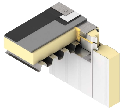
FIGURE 12: Shown is a saw cut in the metal skin of an IMWP to reduce thermal bridging. Image courtesy of Kingspan.
Penetrations in the field of the roof are potential locations for air leakage, thermal loss and condensation. An equivalent effort to air seal should be made at penetrations in the field of the roof as is made at the perimeters where the roof meets the wall. Typical details often do not specifically address air sealing, and certain details like ganged penetrations are difficult to air seal.
Standard details typically show the insulation butting up to a vertical penetration, like a pipe. The addition of spray foam between the edges of the insulation and the penetration makes an effective air seal at that location. The air-control layer should be connected to the spray foam to provide a continuous air barrier; for cold storage buildings, the air seal around the pipe should tie to the roof membrane that is acting as the air-barrier-control layer. Figure 13 shows this condition.
Pipes in roofs and walls may move due to thermal expansion and contraction as well as vibration, so it’s important to select pipe penetration flashings that can accommodate movement, such as pre-manufactured flashing boots. Figure 13 also shows this idea.

FIGURE 13: Shown is air sealing around a pipe penetration and a flexible pre-molded flashing boot. Graphic courtesy of Roof Spec Inc.
Curbs are also potential locations for air leakage, thermal loss and condensation. Again, proper air sealing at curbs is important for long-term performance. However, the rooftop unit may allow airflow. Continuing the air-barrier layer up the vertical wall of the insulated curb isolates the rooftop unit from the roof system.
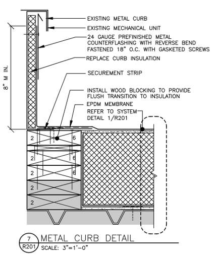
FIGURE 14: Shown is air sealing around a rooftop curb. Graphic courtesy of Roof Spec Inc.
A continuous air barrier is a combination of interconnected materials and systems that require sealed joints and connected components to properly minimize air leakage into or out of the building enclosure. During the design process, architects can use the pen test to trace the air-barrier layer around the entire building (without picking up the pen from the paper), focusing on the perimeters and penetrations, and subsequently addressing the details in the contract documents, to help determine where potential air leakage may occur.10 Ultimately, the architects and designers are responsible for determining the need for an air barrier, verifying an air barrier’s compatibility with other materials, identifying all air-barrier components of the enclosure, and providing construction details for joints, penetrations and transition areas.
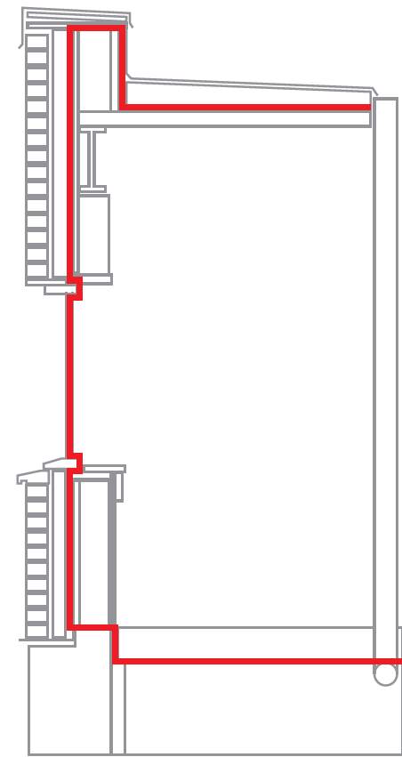
FIGURE 15: Shown is a continuous air barrier that can be traced by using a pen without picking up the pen from the paper. Graphic courtesy of GAF.
Winter Construction
During new construction of a cold storage building, construction-generated moisture can move up into the roof system. This moisture can come from curing of concrete floors and roof decks, the use of propane heaters, and/or ambient humidity and rain. If the moisture is trapped in the roof system, the bottom portions of the insulation can freeze during operation. This concern warrants the use of an air barrier/vapor retarder at the deck level to keep construction-generated moisture out of the roof system. However, an air barrier that is vapor open (a Class III or higher vapor retarder) will allow some drying potential during operation of the building while preventing moisture-laden air from getting up into the roof system during construction. Figure 16 shows an example of this.
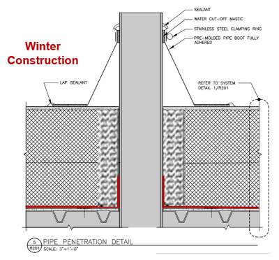
FIGURE 16: Shown is a vapor retarder installed as an air barrier to help prevent construction-generated moisture from infiltrating the roof system. Graphic adapted from Roof Spec Inc.
Also, simply due to cold temperatures, especially with interior spaces below minus 32 degrees Fahrenheit, adjacent materials can become frozen, regardless of air and vapor control. It’s singularly a temperature issue. To that end, the bottom portions (perhaps an inch or two) of insulation can, over time, become frozen, resulting in an effective R-value of zero as well as creating reroofing issues when trying to remove frozen insulation.
Reroofing Concerns
Reroofing a cold storage building provides a unique opportunity to identify and address air and vapor leaks that may be occurring. This is a critical step for long-term success and proper performance not only of the roof but also the building itself. This is the benefit of a reroofing project—problems can be located and solutions determined prior to reroofing.
According to the requirements of the building code, wet insulation is required to be removed prior to reroofing (for re-covering and replacement projects). Frozen insulation is ‘wet’ and has little, if any, insulating value. Most commonly, frozen insulation is located just above the deck. This may also be indicative of some level of moisture intrusion into the roof system. The lowest layers of insulation are also the coldest; they are adjacent to the cold portion of a cold storage building. Determining the source of moisture and addressing the issue (e.g., including a Class III vapor retarder at the deck level) can improve the thermal- and moisture-control performance of the roof and the entire building.
Testing
The air-barrier-control layer can be tested as a material, system or whole building according to the International Energy Conservation Code. For cold storage buildings, it’s prudent to use whole building air-leakage testing as a measure to ensure the enclosure air leakage is minimized to save energy, prevent moisture (or ice) accumulation and enable the refrigeration system to perform as intended.
In general, whole-building air-leakage tests should be performed when the air-control layer is exposed and repairable without significant deconstruction. Therefore, timing of a whole-building air-leakage test is critical because it’s extremely difficult and expensive to deconstruct a completed building and then repair the air-control layer. For cold storage buildings, the timing concern is less critical because the roof membrane and the exterior wall skin is the air-control layer.
In Summary
Avoiding thermal bridging by using adhered membranes and adhered upper layers of insulation, with only the bottom layer(s) mechanically attached, allows for a more effective thermal layer. Reduce or eliminate air leakage across the building enclosure to reduce the potential for moisture gain, condensation and freezing of insulation, as well as heat loss that is associated with air infiltration and exfiltration. Details make all the difference in this case. Consider expansion and contraction potential as well as differential movement when designing the details at interfaces and penetrations to extend the service life and functionality of the roof’s details.
And finally, cold storage buildings are unique because of their low interior temperatures and the resulting vapor drive and significant potential for air infiltration. Taking into account the science of heat, air and moisture movement when designing the roof system for a cold storage system is paramount for long-term success.
References
1. “Energy Modeling Guideline for Cold Storage and Refrigerated Warehouse Facilities.” International Association for Cold Storage Construction and International Association of Refrigerated Warehouses. 19 December 2013. Web. 23 June 2020. <www.gcca.org/sites/default/files/protected-docs/protdocs/EnergyGuidelines_2013-12-19.pdf>.
2. Zhivov, Alexander and Herron, Dale. “Improvement of Air Tightness in U.S. Army Buildings.” Journal of Building Enclosure Design. Summer 2011. Web. 23 June 2020. <cdn.ymaws.com/www.nibs.org/resource/resmgr/jnibs/jbed_summer11.pdf>.
3. Cleaning the Air on Air Barriers: A Guide to Air Barriers in Commercial Low-Slope Roof Assemblies.” GAF Technical Services. April 2018. Web. 23 June 2002. <www.gaf.com/en-us/document-library/documents/commercialroofingsystems/everguardpvc/a_guide_to_air_barriers_in_commercial_lowslope_roof_assemblies.pdf>.
4. Kirby, James R. “Air Barriers and Vapor Retarders: The Current Conundrum in the Roofing Industry.” GAF Blog. 10 September 2018. Web. 23 June 2020. <blog.gaf.com/air-barriers-and-vapor-retarders-the-current-conundrum-in-the-roofing-industry/>.
5. Energy Modeling Guideline for Cold Storage and Refrigerated Warehouse Facilities.” International Association for Cold Storage Construction and International Association of Refrigerated Warehouses. 19 December 2013. Web. 23 June 2020. <www.gcca.org/sites/default/files/protected-docs/protdocs/EnergyGuidelines_2013-12-19.pdf>.
6. Hardy Pierce, Helene and Crowe, Joan P. “Structural Concrete Decks, Vapor Retarders, and Moisture – Rethinking What We Know.” Interface Magazine. February 2020. Web. 23 June 2020. <iibec.org/wp-content/uploads/2020-02-pierce-crowe.pdf>.
7. Gatto, Kip; Wong, Grace; and Klaboe, Kari. Assessing Concrete Moisture in Unconditioned Environments.” Proceedings from the 33rd RCI International Convention and Trade Show. March 2018. Web. 23 June 2020. <iibec.org/wp-content/uploads/2018-cts-gatto.pdf>.
8. A Guide to Cold Storage Roof System Design.” GAF. November 2019.
9. Taylor, Thomas J.; Willits, James; Hartwig, Christian A.; and Kirby, James R. “Insulation Value Optimization for Low-Slope Roofs.” RCI Building Envelope Technology Symposium. November 2018. Web. 23 June 2020. <www.gaf.com/en-us/document-library/documents/documents/architectsandspecifiersdocuments/insulation_value_optimization__201811.pdf>.
10. Meyer, Benjamin. “Parapets Part 1: Continuity of Control Layers.” GAF Blog. 27 September 2019. Web. 23 June 2002. <blog.gaf.com/parapets-continuity-of-control-layers/#:~:text=To%20better%20understand%20common%20parapet,sides%20of%20the%20building%20enclosure>.
Complete the quiz and receive a certificate of completion
EARN: 1 AIA LU/HSW; 1.5 GBCI CE HOUR; 0.1 IACET CEU; 1 IIBEC CEH // AIA COURSE #BE2020B
Looking for a reprint of this article?
From high-res PDFs to custom plaques, order your copy today!
.webp?height=740&t=1767036885&width=auto "Header - BE 1170x658 (002).png")

.webp?height=740&t=1755781744&width=auto "KEE(2).png")