Sponsored by GAF
CEU: High-Performance Cold Storage Roof Design
Bundle Up, It’s Cold Inside!
All images courtesy of GAF, unless otherwise noted.
AIA course number: BE2023GAF1
Credit Type(s): 1 AIA LU/HSW; 1 IIBEC CEH; 0.1 IACET CEU
Learning Objectives:
After reading this article, you should be able to:
- Review the importance of air, vapor, and thermal control layer continuity.
- Evaluate how cold storage roof design can impact building energy use and operations.
- Assess typical cold storage details to appraise control layer continuity.
- Examine common installation and detailing errors during construction and how they impact roof functionality.
Complete the quiz and receive a certificate of completion!
Credits:


Section 1: Defining Cold Storage Buildings
Cold storage refers to a building or portion of a building designed to promote extended shelf life for products or commodities. Cold storage buildings can house various industries including food processing plants, pharmaceutical manufacturing facilities, and holding facilities for dry, refrigerated, and frozen goods. Typically, these structures have year-round temperatures below 50 degrees Fahrenheit (10 degrees Celsius). There are varying levels of cold storage, such as coolers, chill coolers, holding freezers, and blast freezers. Coolers range from approximately 32–55F (0–13C), while, at the other extreme, blast freezers can have interior temperatures from minus 20–50F (minus 29–46C).
Cold storage buildings are exceptional structures because they experience extremes in both internal temperature and humidity compared to typical buildings. Due to their distinctive nature, cold storage buildings require unique construction assemblies, including roof assemblies.
The marked difference in vapor pressure between the building interior and the exterior can cause a pronounced vapor drive through the roof assembly. When warm humid air that infiltrates into the roof assembly there can be extreme consequences including significant build-up of condensation within the roof assembly, or even inside the building, if the roofing system is not properly designed and installed. These factors can lead to severe deterioration of both the roof assembly itself and interior components, as well as damage to stored goods and health and safety concerns for employees.
It is both the challenge and the responsibility of the design professional to correctly specify the cold storage building type and its roofing system. Careful selection of primary control layers of water, air, thermal, and vapor, and design of their continuity will aid the roof in its role of reducing the risk of condensation. High-performance roof design is essential to operations efficiency and decreased energy use of the cold storage facility.
Section 2: Cold Storage and Building & Roofing Science
Temperature and thermodynamics. Relative moisture risks. Vapor control materials. Air transport and air leakage. All of these elements are inputs into the equation of a high performance roof. Failing to plan for even one of these, or planning incorrectly, frequently results in energy loss and inefficient operations. This is especially true for a cold storage facility.
Why is a cold storage building so different? Cold storage is not a typical building simply because of its temperature, but due to the temperature differential between the interior and the exterior, and the resulting vapor drive from the exterior to the interior is significant. Because cold storage buildings are maintained at temperatures that are often much lower than the exterior temperature, the warm, moist, outside air wants to move to the interior of the building to achieve equilibrium. The direction of the vapor drive is predominantly from the exterior to the interior for most times of the year since in most climates the interior will be colder than the exterior.
While a concern is the vapor drive that occurs from the warmer exterior toward the colder interior, air infiltration into the interior of the cold storage building is a greater concern and can have detrimental effects to the roof assembly. Combating this requires two critical measures in the roof design: first, proper placement of a vapor retarding material to manage the vapor drive and second, proper detailing to prevent air infiltration at enclosure transitions and penetrations.
Condensation control
A common way to control or minimize condensation problems in a roofing assembly is to use a vapor retarder. Vapor retarders help reduce vapor diffusion into a roof system. The most common uses of vapor retarders occur in buildings located in colder climates, over concrete decks, and for buildings with high interior humidity levels, such as swimming pools, museums, and data centers. In these scenarios, the most effective location for a vapor retarder is directly above the roof deck and below the roof insulation layer, or in some cases, directly above a rigid board, like gypsum board, that is secured to the roof deck. The vapor retarder restricts moisture from the building interior into the roof assembly. This location of the vapor retarder is installed on the warm side (in winter) of the insulation.
Although the same principle applies for cold storage buildings, because the vapor drive is generally from the warm to cold, the vapor retarder is located on the exterior side of the insulation. This is generally true for most geographical locations in the U.S. for most months of the year; the interior is most often colder than the exterior of the building. Most commonly, the roof membrane serves as the vapor retarder; using the roof membrane as the vapor retarder places unique needs on any membrane selected.
In a typical cold storage configuration, the roofing membrane will act as both the vapor retarder and air barrier, keeping both vapor and air from getting into the roof system. However, successful installation and detailing are key to prevent air and vapor intrusion into the building interior and roof assembly. If heat and moisture reach a cold surface, this can create condensation. When condensation reaches the insulation, the insulation’s performance is reduced, which includes a reduction of R-value and equates to energy loss within the building. Condensation can also occur at building interiors such as at the underside of roof decks or on storage floors, which can impede interior operations.
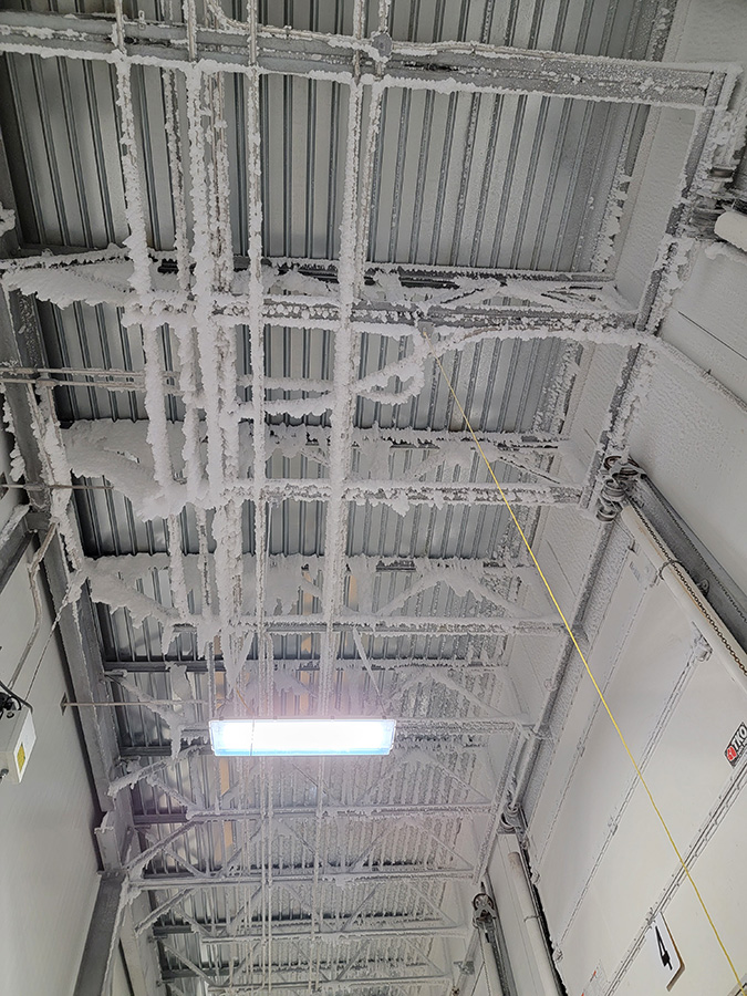
Ice formation on the underside of the roof deck.
Fundamentals of moisture control
One of the primary purposes of a building envelope is to keep moisture out of a building. What makes this seemingly simple goal a challenge is that moisture comes in many forms and can take many paths into a building. Building designers need to account for bulk water, air-transported moisture, and water vapor, and defend against each of these in different ways.
Bulk water
Bulk water, such as rain and snow, is kept out of buildings with roof membranes and wall cladding systems. Roofs were first created for this purpose, and keeping out bulk water consists of watertight detailing that is typical for any roof assembly. Cold storage detailing requires augmenting of typical roof details to include air tightness in conjunction with water tightness.
Air-transported moisture
Air-transported moisture, as the name implies, is carried into or out of a building by air that infiltrates or passes through the building envelope. In a warm climate, air transports up to 10 times more water than diffusion, and in a cold climate, air transports up to 100 times more water than diffusion. To complicate this, there are several types of air transportation that can occur through the building envelope. Air infiltration is where exterior air enters into the building through gaps in the exterior enclosure. In cold storage, this can be problematic since most often the exterior air is warmer and more humid than the interior, which can lead to condensation when the warm air meets a cold surface.
Exfiltration is where interior air exits from the building, also through gaps and inconsistencies in the building exterior. Exfiltration can lead to the cooling systems having to work harder to maintain interior temperatures, which ultimately leads to higher energy bills. Intrusion is air that enters a roof or wall system but does not exit to the exterior; an air barrier prevents the passage of air through the entire building enclosure. Since air that enters from the exterior often contains moisture, condensation is likely to form as a result, often forming within the roof assembly. Condensation within the roofing assembly is not likely to evaporate, and instead this can lead to frozen insulation and roofing components. This is why air-transported moisture is much more critical to prevent than water vapor that enters a building by diffusion; condensation is likely to occur at any time there is uncontrolled air movement.
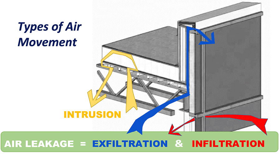
Air transportation.
Vapor drive
Cold storage buildings are commonly maintained year-round at temperatures that are, in most geographical areas and for most of the year, considerably lower than the exterior temperature. For cold storage buildings, the warm, moist outside air wants to move inward. This means the direction of the vapor drive experienced by a cold storage structure is opposite that of a conventional building—from the exterior to the interior. Therefore, the importance of a continuous vapor retarder from on the exterior of the building, such as the roof membrane, is critical to inhibit vapor diffusion.
Air leakage versus vapor diffusion
Because of the comparative amount of moisture transported during each process, air-transported moisture is a larger issue than vapor diffusion. The National Research Council Canada collected research data that illustrated how even small openings can dramatically affect overall air leakage performance.1 For example, air can transport up to 100 times more moisture than the process of diffusion. This illustrates the greater impact that air leakage can have over moisture accumulation from vapor diffusion, which can have a significant negative impact on cold storage facilities. Air leakage can form ice or icicles on the underside of roof decks or within the roofing assembly, all of which impact the energy use and operations within the cold storage facility.
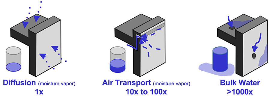
Relative moisture risks.
Most commonly in cold storage structures, the roof membrane serves as the vapor retarder and the air barrier. Accordingly, it is critical that the membrane be continuous, with no gaps or holes. The membrane should be designed and installed to block the passage of air by detailing all laps, penetrations, and the roof-to-wall interfaces. Any discontinuities within the assembly will lead to condensation within the roof assembly or at the interior of the cold storage facility.
Section 3: Cold Storage Design
There are many factors that may affect roof design, including specific jobsite conditions, local building codes, and building use, all of which must be taken into account to achieve desired energy savings and efficient operations. Due to the nature of cold storage buildings and the need to maintain specific interior temperatures, designing the best roofing system for the building becomes more than material selection. Proper design and installation will impact the functionality of the roof assembly for the life of the roof, which could be 20 years or more.
Cold Storage—General design considerations
Proper roofing system design and selection involves careful consideration of factors specific to cold storage. These help to provide a fundamentally sound basis for design and selection. First, verify during design that proposed materials are compatible with each other and that they will achieve the end goals of the project, such as energy efficiency and mitigation of air movement.
Section 4: Roofing Assembly Design in Cold Storage Buildings
A successful building system is greater than the simple sum of its parts. That is especially true for buildings facing challenging performance issues, like cold storage buildings. Material selection is extremely important, but how the entire system interacts and reinforces itself is of equal weight. Given their unique thermodynamic needs, a cold storage building should have an uninterrupted, continuous building envelope. That envelope should provide adequate levels of insulation to maintain interior temperature and minimize thermal loss as well as control air and vapor intrusion across the envelope. Material selection as part of a roofing assembly will determine how effective the roof will perform over the life of the roof system.
Ultimately, a cold storage building should have an uninterrupted, continuous building enclosure with these attributes:
- Adequate amounts of insulation.
- Appropriate attachment to maintain interior temperatures and minimize thermal loss.
- Control of air and water vapor movement.
- Design that anticipates low interior temperatures, the resulting vapor drive, and significant potential for air infiltration. This includes proper detailing to prevent air infiltration or exfiltration at enclosure transitions and penetrations.
Vapor retarders
The climate in which a cold storage building is located is a factor in determining where to install the vapor retarder. As discussed previously, in most locations for most times of the year, the interior of the building will be colder than the exterior. Therefore, the most effective place for a vapor retarder is at the exterior of the roofing assembly, which most often is the roofing membrane. Most roof membranes are Class I vapor retarders; perm ratings for single-ply membranes range from 0.03 to 0.06 perms. The lower the perm rating, the less diffusion of water vapor that occurs through a material. It is important to note that these are material ratings; the full system needs to be designed and installed correctly for proper functionality.
Membrane
The roof membrane will need to provide protection against the damage caused by heat, weather elements, and UV rays. The membrane chosen should have the appropriate levels of puncture resistance, particularly for buildings where there will be increased traffic on the roof due to maintenance of cooling equipment. For roof membranes facing the risk of hail, the membrane should be a higher performance reinforced membrane as part of an assembly that has the appropriate hail rating.
The selected membrane should also demonstrate dimensional stability, which means that the material will not shrink over time. Materials that are prone to shrinkage will pull away from vulnerable areas such as at parapets, where the roof deck to parapet wall interface is a crucial interface to limit air infiltration into the assembly.
Selecting a reflective white membrane can help to reduce building cooling costs by lowering the roof’s ambient temperature. Reflective membranes will reflect the sun’s rays and will prevent the heat from entering into the building. Using a lighter colored roof can decrease the urban heat island effect in cities and also may decrease the amount of heat that is able to radiate into a building’s interior.
Membrane seam strength is another area of analysis. Membranes typically feature either welded, taped or glued seams. Heat-welded seams tend to provide better long-term performance over taped seams as welding creates a monolithic material and the seam becomes the strongest point of the membrane. Glued or taped seams over time can lose adhesion and can create points on the roof that are susceptible to water infiltration—and in the case of cold storage facilities—air infiltration.
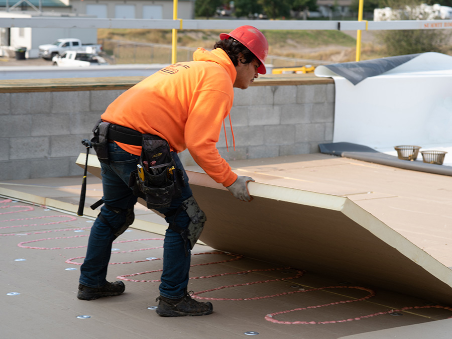
Installing insulation. Insulation is critical in roofing assemblies for overall energy efficiency of the building.
Insulation
Insulation plays a critical role in the building enclosure performance of a cold storage building. To minimize the potential for interior condensation, appropriate amounts of insulation should be used so that the interior effectively maintains the cooling set points. Insulation type should be evaluated for R-value and other desired material properties such as water vapor permeance, water absorption, and compressive strength.
When selecting insulation for a cold storage roof, there are many choices available. Each one has different characteristics and properties. Generally, possible insulation choices include polyisocyanurate (polyiso), expanded polystyrene (EPS), extruded polystyrene (XPS), mineral wool, and lightweight insulating concrete (LWIC). Make sure that the insulation selected is a good fit for the entire roof system, is compatible with other systems, and meets required code.
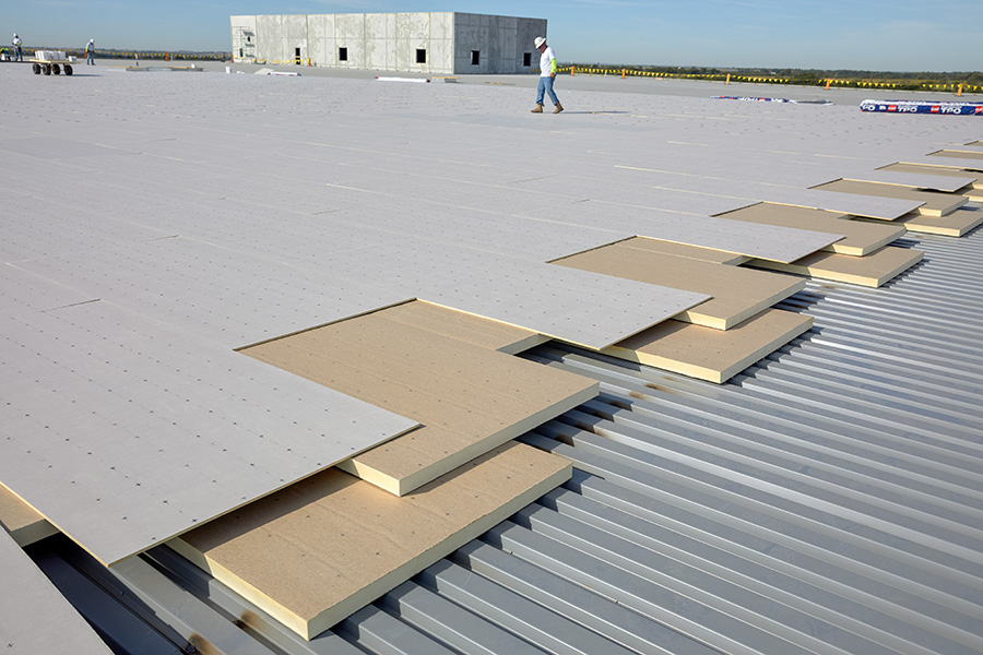
Insulation boards are staggered and offset to prevent aligned joints from forming a clear path for any air and moisture intrusion.
Insulation is critical in roofing assemblies for overall energy efficiency of the building. The higher the R-value, expressed per inch, the better the thermal performance of the insulation and its effectiveness at maintaining interior temperatures. Higher R-value per inch means less material is required to achieve the desired insulating value. Insulation boards are required by code to be installed so that the joints are staggered and offset, and several layers of insulation should be installed rather than just one thick layer. To enhance thermal efficiency, plan for multilayer insulation, where fasteners are buried within the system. Designs with the first layer mechanically attached and the upper layers adhered are shown to be most effective for cold storage roofs. Staggering and offsetting the insulation board joints prevents a clear path for any air and moisture intrusion.
It is the designer’s responsibility to determine the appropriate amount of roof insulation. The 2018 edition of the American Society of Heating, Refrigerating and Air-Conditioning Engineers’ (ASHRAE) ASHRAE Handbook—Refrigeration, is a resource where R-values are recommended by interior temperature. In general, the colder the interior temperature, the more insulation is recommended.
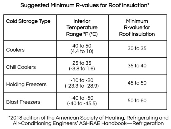
ASHRAE suggested minimum R-values
Coverboards
Inclusion of a coverboard must be considered during roof assembly material selection. Cold storage roof assemblies generally have increased foot traffic on the roof due to the presence of cooling equipment that is often located on the roof. Coverboards not only provide added protection against foot traffic, but also penetrations, including from tools dropped by service contractors and wind-borne debris. If hail is a concern, there are various coverboards that provide hail ratings for Severe Hail to include high-density polyiso and gypsum based roof boards, as well as Very Severe Hail to include glass mat boards.
Roof attachment method
The attachment method of the roof assembly, whether mechanically attached or adhered, should be evaluated during the design phase and align with performance expectations. As part of determining the attachment method, the effects of the attachment method as it relates to the energy efficiency of the system should be reviewed. As such, identifying thermal shorts and the reduction or elimination of thermal bridges are vital considerations. Thermal bridging occurs when heat passes through a material that is more conductive than the surrounding materials. Insulation is great for reducing heat flow, but the mechanical fasteners that are used to install roof assemblies are great conductors of heat, and can reduce the overall effectiveness of the surrounding insulation.
To reduce the effects of thermal bridging between the gaps between insulation boards, roof insulation should be installed in at least two layers with offset joints to minimize air leakage and movement. Likewise, to reduce the effects of thermal bridging from mechanical fasteners, fasteners should be buried within the system. The first layer of insulation, that is the layer in direct contact with the roof deck, may be mechanically attached. However, subsequent layers should be installed with adhesives to avoid thermal bridging caused by fasteners that are installed through the entire assembly. It is also recommended that the coverboard and roof membrane be adhered to the insulation. Relying solely on mechanical fasteners as the securement method for a roof assembly, or at the upper layer of rigid board insulation, allows thermal bridging to occur and is less energy-efficient. Energy efficiency equates to the cooling equipment not having to run as often to maintain interior temperatures, which will save the building in operating costs.
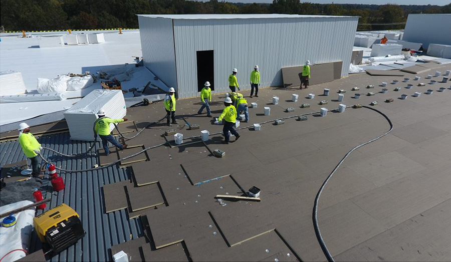
The first layer or layers of insulation, including the layer in direct contact with the roof deck, may be mechanically attached. Subsequent layers of insulation should be installed with adhesives to avoid thermal bridging caused by fasteners.
Photo courtesy of Sun Roofing Co.
Details
In the end, a successful project all comes down to the details; and the details of a cold storage roof are critical in preventing air and vapor transmission. The forces of moisture and vapor drive, thermal control, and air infiltration come together at the intersections of systems and penetrations.
Under the 2015 International Energy Conservation Code (IECC) Section C103.2.1, including more recent versions of the code, the building’s thermal envelope must be represented on the construction documents. The IECC code regulates the design and construction of buildings for the effective use and conservation of energy over the useful life of each building. Beginning at the large scale, a cold storage building should have an uninterrupted, continuous building enclosure across all size sides of the building. This means verifying across the entire building that all interconnected materials and systems are sealed and connected as required to properly minimize air leakage into or out of the building enclosure. Designers can use the “pen test” to trace the continuous layers for each detail, without picking up the pen from the paper, focusing on the perimeters and penetrations. Each layer, such as water, thermal, and air, should be interconnected from the roof to the walls, to below the slab. The pen test will identify gaps between materials that will allow for thermal bridging, water infiltration, or air infiltration.
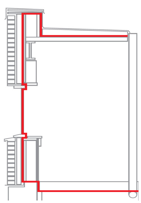
Using a “pen test” verifies that all materials and systems are properly interconnected and sealed, preventing air leakage.
The roof on most cold storage structures acts as both the vapor-control layer and the air-control layer for cold storage buildings. Keeping adjoining systems connected and getting details correct ensures success or failure of the roof assembly. Details must be provided for joints, penetrations, and transition areas, and ensuring these details are airtight is paramount.
Steel Deck Considerations
Special attention should be paid to steel roof decks, which are used in many cold storage buildings.
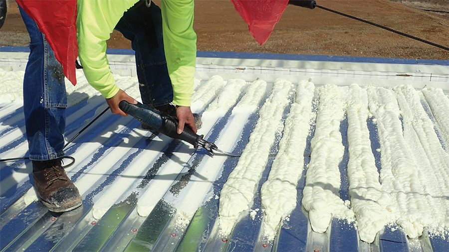
To prevent steel deck flutes acting as a path for air, flutes should be filled with closed-cell spray polyurethane foam.
Image courtesy of Matt Dupuis.
Steel decks pose a particularly difficult detailing issue in regard to air control since they are challenging to air seal at walls and penetrations. Steel decks with flutes can serve as pathways through for the cold interior air to meet with the warm exterior air that enters into the roofing assembly via poorly detailed penetrations and wall intersections. To minimize airflow and create an air seal, steel deck flutes should be filled with closed-cell spray polyurethane foam (SPF) at exterior walls, interior walls that separate different interior climates such as dry storage and a deep freezer, and penetration locations.
Closed-cell spray polyurethane foam should also be used at transitions at interior walls that separate different interior temperature conditions.
Image courtesy of T. Quigley.
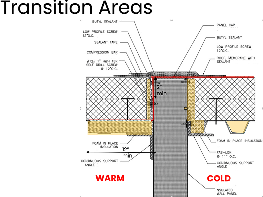
Transition area detail.
At wall to roof deck intersections, SPF should be placed in deck flutes, regardless of the direction the flutes are running in respect to the wall, a minimum of 12 inches measured from the wall. A similar rule of thumb applies to penetrations, where the surrounding deck flutes should be filled a minimum of 12 inches around the penetration. The SPF should be allowed to rise and then cut flush with the surrounding deck flutes so that the insulation boards will sit flat above the SPF.
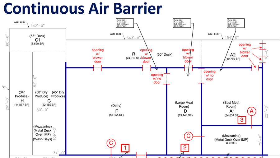
Separation of Interior Spaces
Frequently, cold storage buildings feature different conditioned spaces or rooms within a single facility. Offices, loading docks, and even rooms with varying cooled temperatures such as blast freezers and coolers are often part of a cold storage building. Particularly, spaces with large temperature differentials should be separated not only internally, but at the roof level to prevent air movement from space to space. An approach to accomplish this separation of space utilizes the roof membrane to create a separation at the roof level. The membrane can be turned down between the insulation for each room and adhered to the deck. If a steel deck is used, the flutes should be filled with spray foam insulation to further prevent airflow between the deck flutes.
Accomplish the separation of spaces by utilizing the roof membrane to create a separation at the roof level.
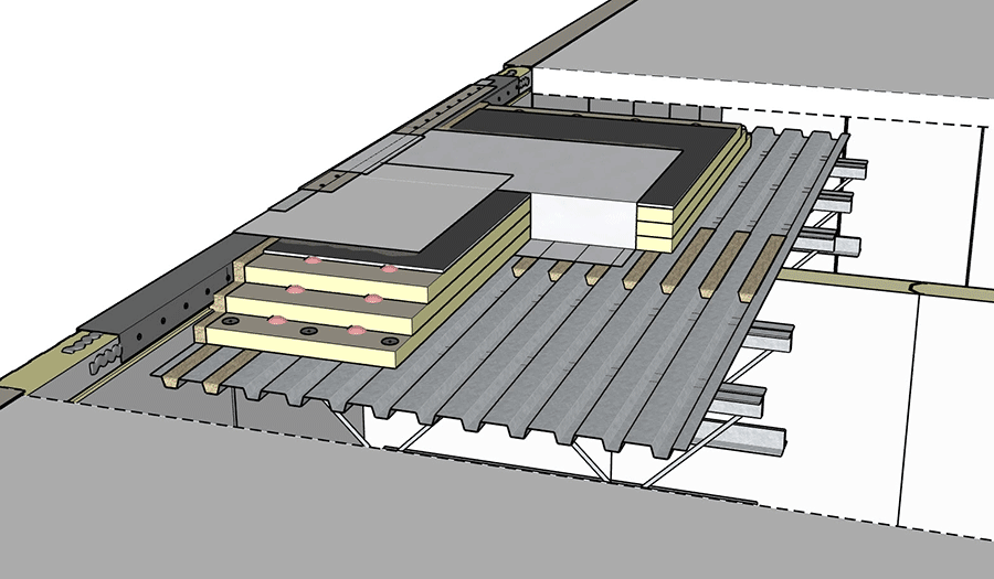
Insulated Metal Panel considerations
Insulated Metal Panels (IMPs) are a common exterior wall assembly used in construction of cold storage facilities. In this type of construction, the connection between the roof assembly and the IMPs are a crucial interface. To complicate this interface, IMPs are often corrugated, which makes terminating flat roofing materials to the surface difficult, which is required to create an airtight seal. On the interior side of the roof, air seals are needed between the face of the IMP and the edge of the insulation boards. This is a critical location for air leaks and condensation potential as this provides direct access to the cooled interior of the building. The most effective way to air seal at this location is to use closed-cell spray foam at the intersection. Prior to installation of the spray foam, a thermal break, or kerf, should be cut into the face of the metal panel to expose the foam core of the panel. (See the IMP manufacturer for details on how to cut in this kerf).
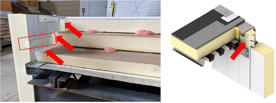
Thermal break, or kerf, cut into the metal panel, prior to the installation of spray foam
Images courtesy of Metl-Span & Kingspan
This allows for foam-to-foam contact and decreases the potential for air to move throughout this intersection of the roof and wall materials. Then, the gap between the rigid insulation and the IMP should be filled with closed-cell spray foam. The rigid insulation should be held back a minimum of 1-inch from the face of the IMP and for the height of the insulation; the gap should be filled with closed-cell spray foam. The spray foam should be allowed to rise and cure and then cut flush with the surrounding insulation boards to create the airtight seal at this location.
Furthermore, the interface between the roof and IMP must be sealed on the exterior side as well. An air seal on the outer and inner surfaces—effectively a double air seal—is an excellent way to block air exfiltration and infiltration. If these interfaces are not air sealed, they can allow airflow, and the moisture contained within, to bypass the air-control layer and enter the building and condense. To create an effective outer air seal, the roof membrane should extend over the exterior face of the IMP and terminate on the outer edge. Similar to the interior face, the exterior face of the IMP is likely to be corrugated, which can create channels for air to travel into the roof assembly. It is a best practice to install a sealant in the low flutes of the corrugations to create a flat surface to terminate the roof membrane. Additionally, if a termination bar is used, sealant or butyl tape should be installed behind the termination bar to further prevent airflow from traveling into the roof assembly.
Section 5: Avoiding Common Installation Mistakes
A high-performing, efficient cold storage roof must do many things at once—it must successfully combat risks associated with temperature and thermodynamics, moisture infiltration, vapor control, and air transport. Unfortunately, because the roof has so many roles to play, mistakes are costly and detrimental to building performance. To ensure that selected materials are installed correctly, only properly trained and professionally equipped roofing contractors experienced in the installation of the selected roofing applications should install these systems over cold storage buildings. The coordination and cooperation of the designer, roofing contractor, and other relevant contractors contribute to a successful installation.
As building science profoundly demonstrates, problems occur when there are paths for air and water vapor movement within the building envelope. It is imperative that the vapor retarder and roof system be continuous, tied to the wall air barrier, and completely sealed at roof penetrations, the roof to wall interface, and other material intersections. It is also highly advisable to limit the number of penetrations through the roof assembly.
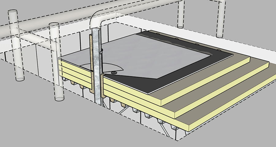
Areas of penetration, like pipes, are areas of concern for air leakage, thermal loss, and condensation.
Errors at penetrations
Penetrations in the field of the roof are potential locations for air leakage, thermal loss, and condensation. Typical roofing details often do not specifically address air sealing, and standard details typically show the insulation butting up to a vertical penetration, such as a pipe. Rigid insulation should be held back a minimum of 1-inch from the penetration and closed-cell spray foam should be installed between the rigid insulation and the penetration. The addition of spray foam, which is not typical to roof details, creates an effective air seal at penetrations. It is important to select pipe penetration flashings that can be installed airtight, such as with the use of a split pipe boot. Often pipe insulation is needed in addition to the roof insulation. The location and installation of the pipe insulation should be coordinated as pipes, such as for cooling equipment, can introduce condensation into the roofing system if not insulated properly.
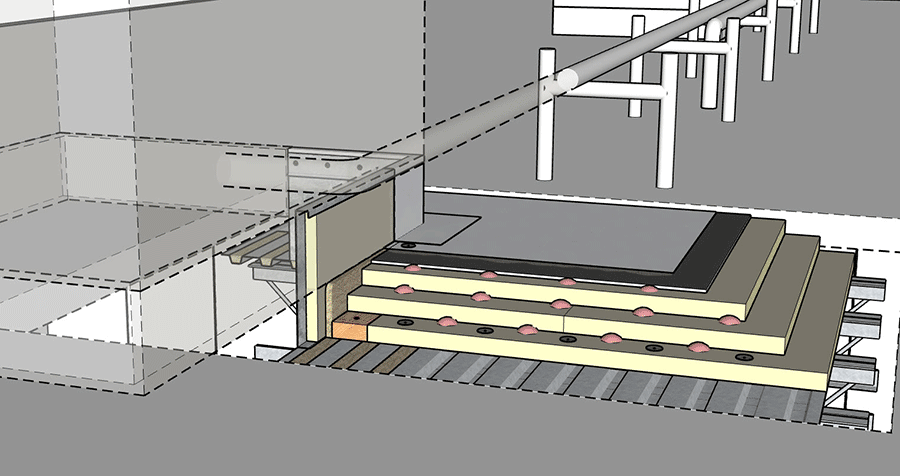
Proper air sealing at curbs is critical to protect against moisture buildup or other deterioration.
Errors at curbs
Curbs, such as for mechanical equipment, are also potential locations for air leakage and resulting condensation. Again, proper air sealing at curbs is important for long-term performance. Similar to the detail for penetrations, rigid insulation should be held back a minimum of 1-inch from the curb and closed-cell spray foam should be installed between the rigid insulation and the curb. The addition of spray foam makes an effective air seal at penetrations. However, mechanical units often sit on steel framing, which is uninsulated and creates a thermal bridge within the roof assembly. The steel framing should be insulated as well; and if there is a steel deck, the deck flutes should be filled with spray foam.
Additionally, during construction, the membrane base attachment method should be discussed with the roofing manufacturer. In normal roofing installations, fasteners are installed around the perimeter of the curbs and penetrations to secure the field sheet of the membrane. This creates additional thermal bridges as the fasteners must span from the top of the membrane down through the steel deck. This allows for air and thermal transfer through the roof assembly. An alternate method would be to secure one piece of wood blocking around the perimeter of the curb to the deck, then install insulation to the designed height, and install the fastener into the blocking, not the steel deck.
Challenges for winter construction
During new construction of a cold storage building, construction-generated moisture can move up into the roof system. This moisture can come from curing of concrete floors and concrete roof decks, the use of propane heaters, or ambient humidity, rain, or snow. If the moisture becomes trapped in the roof system, the bottom portions of the insulation can freeze during temperature pulldown or regular operation. This concern may warrant the use of a vapor retarder at the deck level to keep construction-generated moisture from migrating into the roof system. Selecting an air barrier that is vapor open, such as a Class III or higher vapor retarder, will allow some drying potential during operation of the building while preventing moisture-laden air from getting driven into the roof system during construction.
When moisture laden air is allowed to enter into the roof assembly, the materials can become frozen. Frozen insulation results in an effective R-value of zero, which affects overall energy efficiency of the cold storage facility. Frozen insulation also creates reroofing issues when trying to remove existing insulation from the facility as it most often becomes frozen to the deck substrate and can be quite disruptive to the continued operation of the facility.
Temperature Pulldown
Temperature Pulldown, or Temperature Draw Down, raises another challenge for the cold storage design professional. ASHRAE offers the following temperature pulldown considerations for cold storage buildings in the 2018 edition of the ASHRAE Handbook—Refrigeration:
Chapter 24:
“The first stage of temperature reduction should be from ambient temperature down to 35F, at whatever rate of reduction the refrigeration system can achieve. The room should then be held at that temperature until it is dry.
The concrete slab will contract during pulldown, causing slab and wall joints, contraction joints, and other construction joints to open. At the end of the holding period, any necessary caulking should be done. An average time for drying is 72 hours. However, indicators that may be used include watching the rate of frost formation on the coils or measuring the rate of moisture removal by capturing condensation during defrost.
After the refrigerated room is dry, the temperature can then be reduced again at whatever rate the refrigeration equipment can achieve until the operating temperature is reached. Rates of 10F per day have been used in the past, but if care has been taken to remove all the construction moisture in the previous steps, faster rates are possible without damage.”
The time required for some cold storage facilities to reach the design temperatures could be several weeks. It is important for all finishes within the facility, including roofing, to adhere to the recommended timeline to reach the design temperatures. It is, however, normal to have some contraction of roofing elements since construction materials tend to contract in cold temperatures. It is possible that flashings at penetrations, or termination bars on exterior walls could have slightly shifted during the draw down period. It is important for the roofing contractor to visit the site after the draw down period is complete to re-seal any locations that may have become compromised.
Conclusion
The equation of operations, high-performance roof design, and energy use all hinge on controlling inputs from internal temperature, thermodynamics, moisture risks, vapor control materials, and air leakage. When it comes to designing the roof of a cold storage facility, the details are critical to prevent air and vapor transmission. Cold storage roofing, even more than most construction, requires correct design, quality materials, good workmanship, and close supervision during installation. Design should ensure that proper installation can be accomplished under various adverse jobsite conditions and that materials are compatible with each other. Ensuring an uninterrupted, continuous building enclosure provides a shield that protects both the building’s performance and its longevity.
Complete the quiz and receive a certificate of completion
Earn: 1 AIA LU/HSW-pending; 1 IIBEC CEH; 0.1 IACET CEU
References
1. May 2011. Impact of Air Leakage on Hygrothermal and Energy Performance of Buildings in North America. National Research Council of Canada. NRC Institute for Research in Construction. 13th Canadian Conference on Building Science and Technology. 1-2. NRC-IRC-21657. https://nrc-publications.canada.ca/eng/view/object/?id=4669310e-0f32-45ed-b393-21318c023789.
Looking for a reprint of this article?
From high-res PDFs to custom plaques, order your copy today!
.webp?height=740&t=1767036885&width=auto "Header - BE 1170x658 (002).png")

.webp?height=740&t=1755781744&width=auto "KEE(2).png")


