Sponsored by GAF
CEU: All of the Above: Unburdening Overburden Considerations for Commercial Roofing
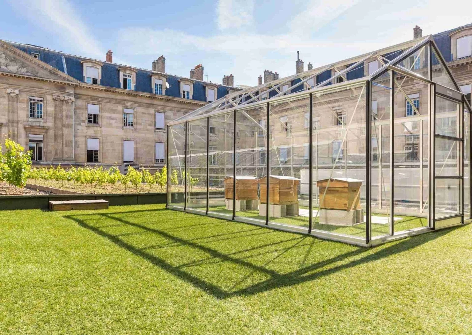
A vineyard and bee hives on the roof of City Hall in Paris. Photo courtesy of Standard Industries.
AIA course number: BE2022B
Credit Type(s): 1.5 AIA LU/HSW; 1.5 IIBEC CEH; 1.5 GBCI CE Hours; 0.1 IACET CEU
Learning Objectives:
After reading this article, you should be able to:
- Define what is meant by overburden on a rooftop.
- Differentiate between vegetative roofs, blue roofs, blue-green roofs, and purple roofs.
-
Understand roofing considerations for rooftop solar PV arrays.
-
Recognize how selection and design of the roof assembly is critical for a long-lasting overburden installation.
-
Review roof assembly design considerations including membrane thickness and color, roof attachment method, presence of a cover board, the importance of continuous control layers, and roof details and flashings.
Complete the quiz and receive a certificate of completion!
Credits:


Let’s Start with a Definition
In roofing, overburden is defined as “any manner of material, equipment or installation that is situated on top of, and covering all or a portion of, a roof or waterproofing membrane assembly.”1
This excludes thermal insulation but includes:
- Planters and everything they contain;
- Vegetative roof assemblies in trays, mats or other similar containers;
- Loose growing media, gravel, sand or any other granular material;
- Non-structural water features, inclusive of the water like water tanks, stormwater retention/detention, etc.;
- Void fill like EPS, XPS, and/or Polyiso rigid foam
- Plaza deck materials like tiles, pavers, supporting pedestals or other similar materials
- Equipment and/or installations like PV arrays2
 Adhered TPO re-roof with solar photovoltaic panels on the Atlantic City Convention Center. Atlantic City, NJ. Photo courtesy of GAF.
Introduction
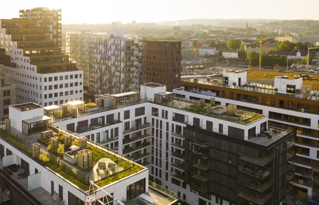
Since its inception a roof’s primary purpose has been to shelter its inhabitants from the elements, but now the underutilized potential of roof surfaces is being realized. For roofs with large surface areas, the potential for large overburden installations, such as solar, vegetative roofing, or amenity decks can be exceptional. Even smaller roofs can have overburden that make a significant impact on the sustainability goals of a building including: increased energy efficiency, rainwater retention, energy generation, biohabitat restoration, food production, reduced urban heat island effect, and outdoor space.
Once thought to be a ‘burden’ for a roofing system, overburden benefits are increasingly emerging as a roofing advancement that's here to stay. In fact, according to Roofing Contractor Magazine, vegetative roofs alone are expected to grow to $14 billion per year by 2026.3 Similarly, according to the Solar Energy Industry Association (SEIA), “Double-digit growth in commercial solar volumes is expected for the next two years.” And, if there is “the passage of federal clean energy incentives, the commercial solar forecast would increase by 21 percent from 2022-2026.”4 Due to the increased frequency and intensity of severe rain-related events, roofs are now considered more often as part of an overall resiliency strategy to reduce flooding from rainwater runoff.
However, selection of the overburden system is only part of the design. Selection and design of the roof membrane, the waterproofing layer that protects the building, is critical for a long-lasting installation. Failure of the membrane, whether it requires repair or replacement, may necessitate removal of the overburden. The removal of the overburden can result in lost energy generation for solar installations, and loss of rainwater capture for both vegetative and blue or purple roof assemblies. Appropriate selection of the entire assembly, including proper detailing and integration of the roof assembly, as well as installation, are paramount to the overall success and longevity of the overburden system.
Overburden for Resilient Design
As defined by the Resilient Design Institute, “Resilience is the capacity to adapt to changing conditions and to maintain or regain functionality and vitality in the face of stress or disturbance. It is the capacity to bounce back after a disturbance or interruption.”5 Climate change related disasters are increasing in frequency, intensity, and cost. Buildings need to be prepared to manage not only the extreme weather related events but also the power outages, and health and safety risks that come along with them. Passive energy efficient design strategies, such as robust continuous insulation and airtightness, ensure that building tenants will be able to shelter in place for extended periods without power and not suffer consequences of extreme heat or extreme cold. By focusing on energy-efficiency first and then adding overburden strategies such as rainwater management, onsite renewables with battery storage, and food production to the roof, building tenants may have little interruption to normal daily activities.
While each property is unique, there are many overburden options and roof assembly considerations to meet increasingly stringent sustainability requirements. After the selection of the overburden type, the roof assembly will need to be determined, which is dependent on the type of overburden and the ultimate use of the roof space. The success of the overburden is dependent on the roof assembly beneath. Installations such as solar or vegetation, the plants and solar array will need to be removed for repairs or replacement. Considerations such as increased foot traffic, overburden movement, and leak detection should all be incorporated into the holistic overburden design. For example, a more robust membrane and integrated leak detection may be warranted for the long-term durability and serviceability of the complete roof and overburden assembly. Another approach is to look at “future-proofing” the roof with a performance-based view to the energy efficiency requirements for thermal insulation, thermal bridges, and air tightness versus simply following the prescriptive code minimum requirements to ensure a long-lasting roof assembly and to minimize the number of roof replacements over the life of the building.
Fun fact: According to Standard Industries, the rooftops of NYC’s 1 million buildings cover nearly 40,000 acres. Under the city’s landmark Climate Mobilization Act, all new buildings must be fitted with solar energy or a green roof. Think of all of the overburden possibilities just in NYC!
 Overburden. Photo courtesy of Standard Industries.
Vegetative Roofs
Vegetative roofs can be installed in trays or built in-place on the roof with extensive or intensive plant configurations. Tray systems and extensive roofs are generally in depths of less than 6 inches and consist of shallow rooted plants, such as sedums. Intensive vegetative roof systems have deeper soil depths and can accommodate larger plant installations. Soil mediums are engineered for specific installations that retain moisture, and are lighter when saturated so as to not overload roof structures. The benefits of vegetative roofs (also called green roofs, living roofs, and garden roofs) are well documented and can help achieve carbon reduction goals, and building resiliency through waste diversion, rainwater management, energy efficiency, increased biodiversity, and urban agriculture.
The benefits of vegetative roofs include and are not limited to:
- Extending the useful life of the roofing membrane by protecting it from expansion/contraction stresses due to temperature extremes, and ultraviolet light degradation.
- Managing and retaining rainwater in the substrate for the plants to use. The retention of rainwater helps not only to reduce the volume of water flowing onto impervious surfaces and into the sewer system, but reduces the strain on aging sewer infrastructure by increasing the speed of the flow of water.
- Increasing thermal efficiency by reducing heat loss.
- Biodiversity restoration in urban areas, which may also reduce the urban heat island effect.
- Reducing the ambient temperature on rooftops, thereby aiding solar arrays to function more efficiently and produce more energy.
- Supplying locally grown agriculture in urban “food deserts.”6
Blue Roofs
Beyond urban agriculture and clean energy generation, rooftops are now also improving on the rainwater management capabilities of vegetative roofs with “blue roof,” “blue-green roof,” and “purple roof” advancements. A blue roof is “a roof designed for the retention of rainwater above the waterproofing element of the roof. Blue roofs are typically flat [or low slope], without any fall, with control devices to regulate drainage outlets that enable water to be retained or drained.”7
“Blue roofs are systems that are designed to provide rainwater detention. Rainfall onto the roof is managed using orifices, weirs, or other outlet devices that control the discharge rate of rooftop runoff. By reducing flow rates from rooftops, blue roofs are effective in reducing the size of downstream detention basins.”8 Blue roofs retain water through passive orifice restriction or detain water through an active mechanical valve or gate apparatus. Similar to a bathtub or sink overflow drain, blue roofs also incorporate an overflow drain to prevent spillover.
 Figure #1
Section detail of a blue roof. Image courtesy of NJ.gov.
Figure #1
Section detail of a blue roof. Image courtesy of NJ.gov.
 Figure #2
Clog prevention for blue roofs. Image courtesy of NJ.gov.
Figure #2
Clog prevention for blue roofs. Image courtesy of NJ.gov.
Blue Roof Considerations
There are a number of considerations for blue roofs to manage rainwater runoff. Including safe rooftop access to the blue roof for maintenance and/or public roof access. The structural load capacity of the roof should also be considered as the retained water on the roof and the catchment system can significantly add weight to the structure. In addition, integrated leak detection strategies and regular inspections and maintenance plans to prevent clogged drains should be incorporated into the design. Considering the longevity and durability of the blue roof accessories and waterproofing layer is of the utmost importance. Leaks are costly to repair and can create a cascade of problems including but not limited to: mold & mildew, poor indoor air quality, corrosion and rotting of building materials, and ultimately structural failure. Extreme care must be taken to ensure that the waterproofing membrane is not damaged. Lastly, rooftop equipment (including solar arrays and electrical connections) should be protected to ensure that it is not damaged as a result of ponding water.9
General Maintenance
According to the New Jersey Stormwater Best Management Practices Manual,
“Blue roofs should be inspected at least four times annually and after every storm event exceeding 1 inch of rainfall. Blue roofs located in areas with significant tree cover or in areas with a high potential for airborne debris may require more frequent inspections due to the potential for clogging. All structural components should be inspected for cracking, spalling and deterioration at least once annually. Disposal of debris, trash, sediment and other waste material must be done at suitable disposal/recycling sites and in compliance with all applicable local, state and federal waste regulations. Access points for maintenance are required on all blue roofs; these access points should be clearly identified in the maintenance plan. In addition, any special training required for maintenance personnel to perform specific tasks should be included in the plan. The design drain time for the maximum design storm runoff volume must be indicated in the maintenance plan. If the actual drain time is longer than the design drain time, the blue roof must be evaluated and appropriate measures taken to return the blue roof to the as-built condition. If the blue roof fails to fully drain within 72 hours, corrective action must be taken and the maintenance manual revised accordingly to prevent similar failures in the future.”10
Potable Water Considerations—NSF P151
Before the introduction of modern drinking water facilities, captured rainwater was one of the best ways to ensure communities had a sufficient supply of water. Parts of the world still rely heavily on rainwater as the main source of drinking water. In order to ensure the safety and health of using captured rainwater for potable water, the NSF established the Rainwater Catchment System Components program, which provides testing guidelines for all components that come into direct contact with rainwater to be used for drinking. The NSF P151 protocol confirms that products do not impart contaminants into the drinking water. When considering using captured rainwater from blue roofs in storage tanks or cisterns, all components should have NSF P151 certification to ensure safe drinking water.11
Blue-Green Roofs
A blue-green roof is a blue roof with a vegetative roof assembly, as well. The added vegetation acts as a biological sponge to reduce the amount of rainwater runoff while, at the same time, slowing the rate at which rainwater runs off. Or, in other words, “The blue green roof combines blue and green roof technologies. Conventional green roofs use a drainage layer to provide lateral drainage and irrigation. Blue roof technology, however, aims to increase both the volume of water stored and control the amount of water released. Combining the technologies can increase the overall benefits of greening roof scapes. Therefore, it is not a case of green or blue infrastructure but a blending of the both”.12
“Blue-green roofs are roof assemblies wherein live vegetation and various substrate layers are used for rainwater detention as part of a stormwater management strategy.13 Blue-green roofs can be distinguished from conventional green roofs in that blue-green roofs provide a larger amount of detention.14 (Temporary storage) of rainwater in addition to existing retention (evaporation) capacities, enhance the roof’s ability to delay and reduce rainwater runoff15 and amplifies the benefits of blue-green roofs in urban areas.”
According to Busker et al, “Runoff reductions during extreme precipitation of 70–97 percent were found.” And, “This is much higher than runoff reductions found for a conventional green roof (12 percent).”16 By reducing runoff, there is less strain on sewer systems and less water flooding impervious surfaces such as streets and hardscapes.
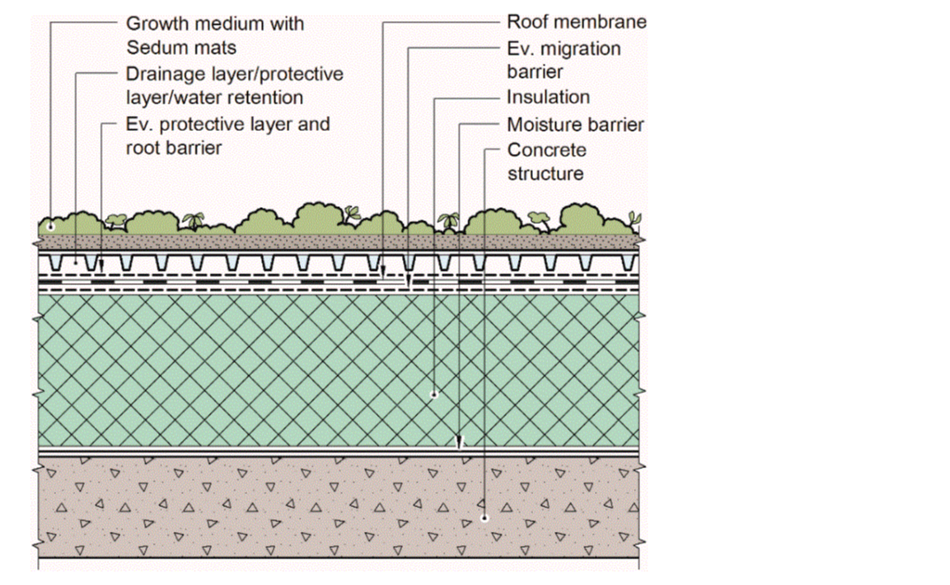 Figure #3
Section detail of a blue-green roof mounted on a conventional roof. Image courtesy of Buildings.
Figure #3
Section detail of a blue-green roof mounted on a conventional roof. Image courtesy of Buildings.
Purple Roofs
A purple roof is a “sponge” roof that incorporates a sponge-like layer made of hydrophilic mineral wool, a dense polyester fabric detention layer, and may or may not include an additional honeycomb layer to increase the volume of rainwater that can be retained and detained and reduces peak outflow by up to 95 percent.17 (See Figure 4).
 Figure #4
Section detail of a purple roof assembly with vegetative roof. Image courtesy of Roof Diagnostics, Inc.
Figure #4
Section detail of a purple roof assembly with vegetative roof. Image courtesy of Roof Diagnostics, Inc.
In addition, purple roofs may or may not include a vegetative roof. Pavers on pedestals for amenity decks can also use purple roof strategies.18 (See Figure 5 & Figure 6)
 Figure #5
Section detail of a purple roof assembly with pavers on pedestals. Image courtesy of Roof Diagnostics, Inc
Figure #5
Section detail of a purple roof assembly with pavers on pedestals. Image courtesy of Roof Diagnostics, Inc
 The layers of a purple roof. Photo courtesy of Roof Diagnostics, Inc.
According to Brad Garner from Roof Diagnostics, Inc., the hydrophilic needled mineral wool layer can reach 50-60 percent saturation before it starts releasing water, or “outflowing.” Once the mineral wool is saturated, the water flows gravitationally into the honeycomb matrix. The honeycomb matrix can be installed in thicknesses from ½-inch to 4 inches depending on the peak rainfall storage needs of the project. The key differentiating factor of purple roofs is the combination of the mineral wool and the added high density polyester fabric detention layer. The detention layer functions like mini gates to detain the water. The mineral wool then dissipates the detained water through evaporation or evapotranspiration through the vegetated layer. The honeycomb layer is added for extra water storage capacity.
 Example of a purple roof diagrammatic hydrograph showing the slow release of rainwater over several days. Image courtesy of SemperGreen USA.
 Example of a purple roof hydrograph showing the peak rain event and the slow release of rainwater runoff over time. Image courtesy of SemperGreen USA.
Rooftop Solar
According to SEIA, “Solar power is energy from the sun that is converted into thermal or electrical energy. Solar energy is the cleanest and most abundant renewable energy source available, and the U.S. has some of the richest solar resources in the world. Solar technologies can harness this energy for a variety of uses, including generating electricity, providing light or a comfortable interior environment, and heating water for domestic, commercial, or industrial use.”19 While there are numerous ways to benefit from the solar energy the sun creates including energy generation, hot water, passive solar heat gains, and passive daylighting; for the purposes of this article, photovoltaic energy generation will be the focus.
“Photovoltaic (PV) devices generate electricity directly from sunlight via an electronic process that occurs naturally in certain types of material, called semiconductors. Electrons in these materials are freed by solar energy and can be induced to travel through an electrical circuit, powering electrical devices or sending electricity to the grid.”20 “Photons strike and ionize semiconductor material on the solar panel, causing outer electrons to break free of their atomic bonds. Due to the semiconductor structure, the electrons are forced in one direction creating a flow of electrical current. Solar cells are not 100 percent efficient in crystalline silicon solar cells, in part because only certain light within the spectrum can be absorbed. Some of the light spectrum is reflected, some is too weak to create electricity (infrared) and some (ultraviolet) creates heat energy instead of electricity.”21
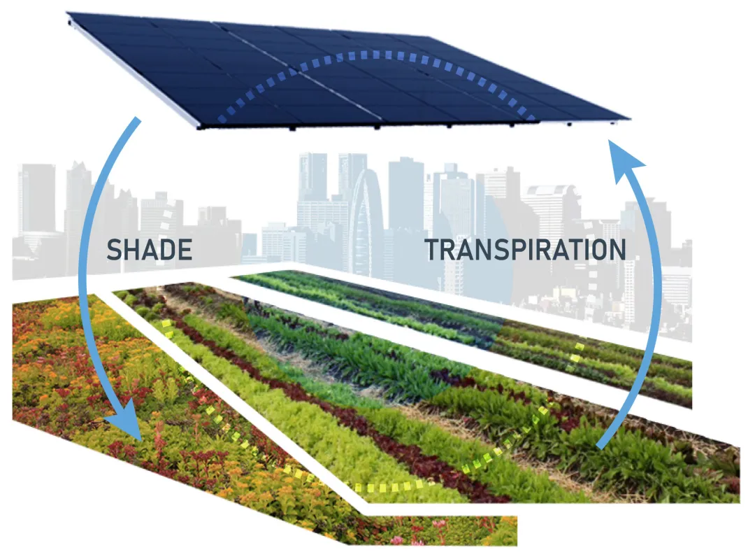 The symbiotic relationship between solar arrays and vegetative roofs. Image courtesy of Sandbox Solar.
Solar PV panels come in both single sided and bifacial (double-sided) modules. A bifacial module can produce power from both sides thereby increasing the energy generation. According to Solar Power World, “When bifacial modules are installed on a highly reflective surface (like a white TPO roof or on the ground with light-colored stones), some bifacial module manufacturers claim up to a 30 percent increase in production just from the extra power generated from the rear.”22
Modules are supported by racking systems on the rooftop that are either mechanically attached to the roof, mechanically attached to a structural canopy that is attached to the roof, or held in place with ballast. For ballasted PV racking systems, it is important to consider whether the roof membrane is adhered or mechanically attached, as discussed in this article. Mechanically attached membranes can billow or flutter in wind events which could put a ballasted solar array in jeopardy of flipping or breaking electrical connections. In addition, the constant movement of ballasted arrays on mechanically attached membranes can damage the waterproofing layer by friction or puncture. Using an adhered roof membrane for ballasted solar arrays can help limit the risk of damage from wind.
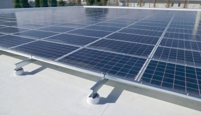 A mechanically attached solar PV array. Photo courtesy of GAF.
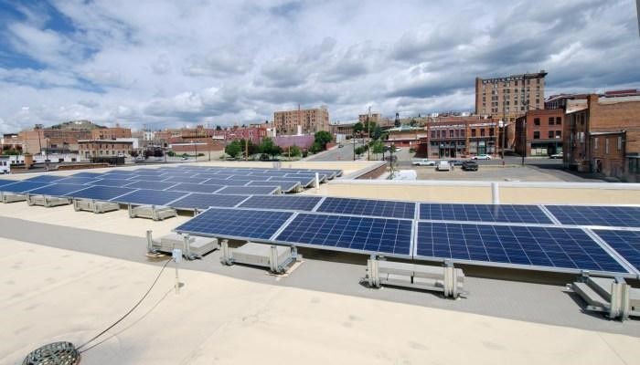 A ballasted solar PV array. Photo courtesy of GAF.
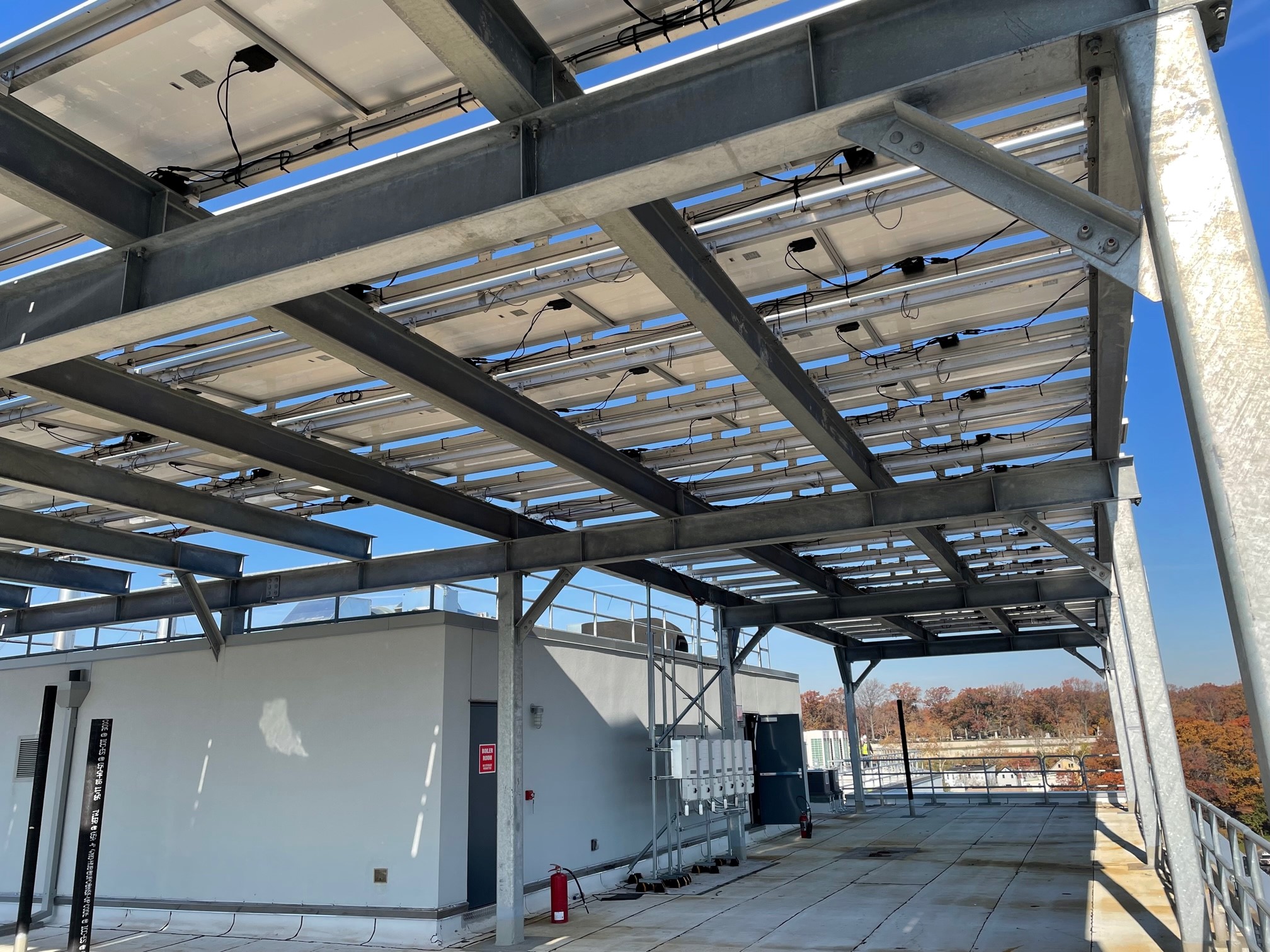 A solar array on a raised structural canopy. Photo courtesy of Shawn Torbert.
Agrivoltaics
Agrivoltaics means ‘“Agri-” relating to food production and “-voltaic” relating to electricity production.’23 The emerging practice of agrivoltaics, or agriculture combined with photovoltaics, is showing promise as a mutually beneficial symbiotic solution to not only increase the efficiency of solar panels, but also increase plant size and crop yields by shading and limiting soil evaporation.
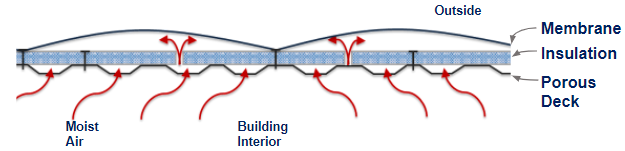 Figure #9
Billowing of a single-ply membrane where the interior air is able to reach the underside of the membrane. Image courtesy of GAF.
Figure #9
Billowing of a single-ply membrane where the interior air is able to reach the underside of the membrane. Image courtesy of GAF.
Janine Benyus, author and Co-Founder of the Biomimicry Institute has asked, “How do we make the act of asking nature’s advice a normal part of everyday inventing?”24 Agrivoltaics does just that. With the solar canopy acting as a forest canopy, plants grow underneath like a forest floor and compete for sunlight. The shade from the solar canopy makes the plants grow bigger. A co-benefit to this approach is that it also conserves water by minimizing evaporation and transpiration. This microclimate created by the solar and vegetation keeps temperatures cooler in warmer climates and helps solar arrays perform more efficiently.
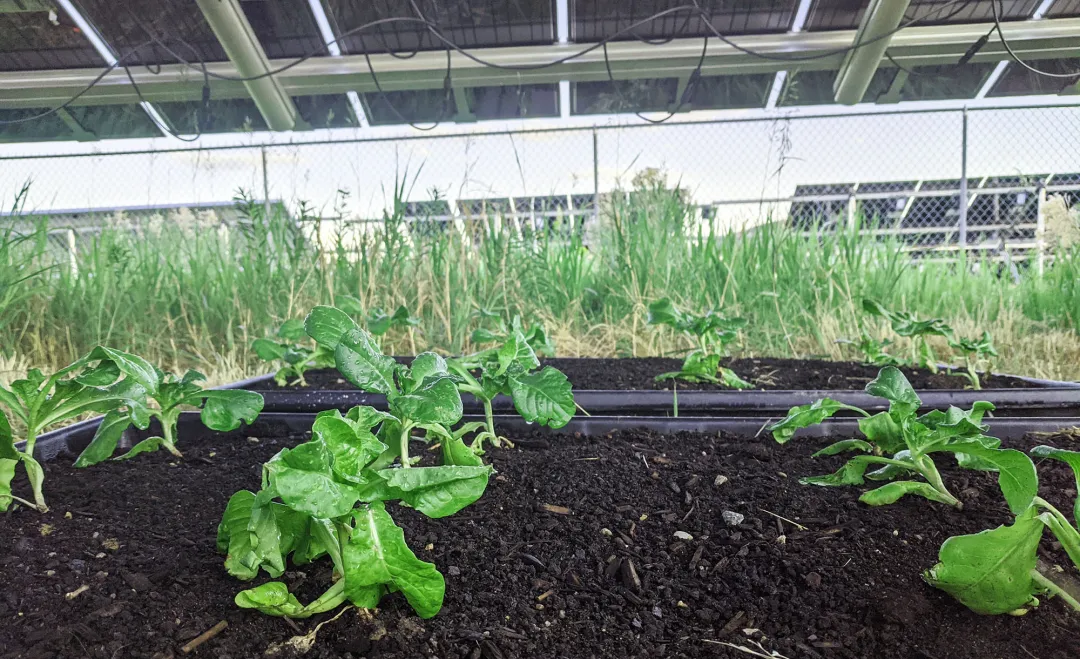 Lettuce Growing in Green Roof Trays under Solar Modules. Photo courtesy of Sandbox Solar.
Similar to all other overburden strategies, Thomas Hickey, a research associate who develops agrivoltaic systems for Sandbox Solar notes “... the challenge is that you can’t just convert any roof to solar agrivoltaics. It has to be flat, for one thing. It might require a significant retrofit to support the extra weight of the soil, plants, and panels. And you’d need to be damn sure it’s waterproofed.”25 This reinforces the benefits of engaging manufacturers and experts specializing in agrivoltaics to support holistic project goals.
Roof System Considerations
While design of the overburden system is important, selection of the roof membrane, the waterproofing layer that protects the building, is critical for the success of the overburden installation. Two main considerations are membrane performance (including color, thickness, and attachment) and roofing assembly configuration, including location of the membrane in the assembly. The improper selection of membrane can result in water infiltration into the building, costly repairs, or even replacement. Special considerations to the type of insulation and the presence of a cover board should be explored. Most importantly, the roof system should be designed to have an equivalent or longer lifespan than that of the overburden systems.
Membrane performance is critical since overburden would require removal in order to repair or replace the membrane. For solar installations, the panels would need to be disassembled, which in addition to the costly labor to remove, storage of panels, potential for panel damage, and the cost to reinstall, also results in lost electricity generation. The ability to easily remove vegetation from vegetative roofs is dependent on the type of roof installed; tray systems may be simpler to remove for replacement, however, storage location and the ability to keep those removed trays alive may prove difficult. Depending on the location of the repairs, the catchment systems for blue or purple roofs may need to be disassembled. Likewise, for a repair, the overburden would need to be removed in order to assess and access the repair location. However, membrane performance is not only dependent on the overburden and associated roofing assembly materials, the design and installation are equally important. The design begins with determining the appropriate roofing assembly including insulation and cover board selection, completing the design down to the last termination and penetration detail, and installing the roof in accordance with the contract documents.
Membrane Selection
Roofing, as with any project, is not a one-size fits all, however, roof system design that aligns with or exceeds the life expectancy of the overburden installations should be considered and is best practice. Project specific considerations should be taken into account to determine the best assembly for the project. The first decision is the orientation of the roofing assembly, including location of the membrane. The type of overburden will determine whether the assembly should be a traditional assembly, where the membrane is on top, or an IRMA (inverted roof membrane assembly) roof where the membrane is at the deck level. For overburden applications such as a vegetative roof, placement of the membrane at the deck level will protect it from possible damage from vegetation roots. When a blue roof is a consideration, placement of a membrane at the top of the roofing assembly is ideal, so that water can easily be collected from the rooftop.
Typical membrane options for roofing assemblies can be considered, including both single-ply and asphaltic based membranes. Comparison of the location, the intended purpose, and service life are fundamental considerations. Membranes that will be used at the deck level should be evaluated for durability and longevity since access to them for repairs will be limited. Typical membrane options at the deck level for vegetative roof systems can be both modified bitumen, and single-ply membranes. Another common waterproofing assembly used at the deck level are hot-fluid-applied membranes. While an excellent choice for vegetative roof installations, without the installation of a cap sheet for UV protection, these would not be considered for a traditional roofing assembly. For the purposes of this article, traditional single-ply and modified bitumen roofing membranes will be reviewed for overburden applications. Typical membranes placed at the top level for solar installations are modified bitumen and single-ply. For blue roofs and water catchment systems, single-ply membranes are commonly used due to performance during ponded water conditions and since they are less likely to leach contaminants into the water. For catchment systems, it is recommended that single-ply membranes meet NSF P151 water standards.
Single-ply membranes include EPDM, TPO, and PVC. The primary difference between the membranes is chemical composition, performance when exposed to chemicals at the roof surface, and treatment of the seams. Single-ply membranes are the most popular roofing membrane today due to their ease of installation and low cost compared to asphalt based materials. Single-ply membranes are, as their name implies, a single layer of membrane roof material and are produced in rolls. The chemical make-up of each of the membranes is different, and therefore, each of the membranes is preferable to different applications. EPDM and PVC perform well when exposed to chemicals, which is an important consideration depending on the building use and overburden type. For vegetative roofing assemblies where fertilizers may be used, all membranes should be checked for compatibility with the chemicals being deposited on the roof. For water collection systems, TPO may be a preferable membrane since it meets NSF P151 water standards. Another difference between the single-ply membranes is the treatment of the seams. TPO and PVC membranes are heat welded at the seams, which produces a monolithic roof membrane. EPDM seams are adhered, which creates a strong seam, but over time, the adhesives may become brittle or deteriorate, leaving open seams in the roofing membrane, which may be problematic for long term performance with overburden systems.
Modified bitumen is a modern day built-up roof that consists of the same asphalt plies, but instead of building the plies on the roof, they are produced in rolls in a factory. Modified bitumen roofs offer the same durable protection of built-up with a faster and more consistent installation since the rolls are pre-manufactured offsite. Modified bitumen roofs have a base ply and a granulated cap sheet (called a two ply system), where the cap sheet provides an excellent wearing surface. Modified bitumen roofs have a high tolerance for chemicals, which makes them suitable for vegetative roof assemblies. While durable, over time, the granules in the cap sheet may become loose. This is typical for granules in a cap sheet, but this type of roofing would not be ideal for blue or purple roofs where there are catchment systems for water as granules may dislodge and collect in the catchment systems.
Membrane selections can further be influenced by color, thickness and attachment.
Membrane Color
For roof assemblies where the membrane is at the top of the system, such as for solar panel installations and blue roof assemblies, the color can have a significant impact on the performance of the system and also on the roof surface temperatures; reflective roof membranes can lower the ambient roof temperature. EPDM membranes are traditionally dark in color and TPO and PVC are typically white or light in color. Modified bitumen roofs can have light colored granules which can increase reflectivity of a roof’s surface. Two roof surface temperatures, differing only by color, can vary by as much as 60 degrees Fahrenheit in the summer heat. Dark colored roofs can reach up to 150F, whereas white or reflective roofing colors can have significantly lower surface temperatures. Using a lighter colored roof can decrease the urban heat island effect in cities, and also may decrease the amount of heat that is able to radiate into a building’s interior. The more heat gain that a roof assembly absorbs, the warmer the interior temperature will be. In the summer, while the heat gain is offset by HVAC systems, the warmer the interior temperature, the longer the systems have to run, which can increase energy use, and potentially raise energy bills.
For solar panel installations, light colored or reflective roof membranes can lower the ambient roof temperature which allows the panels to function more efficiently. The temperature of a PV panel can significantly impact how much electricity the panel produces; as panels get hotter, they produce less power. According to an article published by GAF, “It is estimated that the efficiency of a PV panel can be up to 13 percent higher when installed over a highly reflective membrane compared to a dark membrane with low reflectance. Also, the use of bifacial PV panels over reflective roof membranes can increase the efficiency by 20-35 percent, as they take advantage of the reflected light.”26 For overburden installations, such as blue or purple roofs where the membrane is exposed, it is advantageous to have reflective membranes. While the roof may not always be holding water, or presumably when water is present it is relatively translucent, a reflective membrane will contribute to lowering roof surface temperatures. Lower overall surface temperatures can contribute to mitigating the heat island effect and heat gain into the building interior. Additionally, vegetative roof systems can take advantage of reflective membranes where vegetation is not installed. Codes require that borders and paths are maintained on the roof for fire, access, and maintenance. Reflective membranes at these locations may lower roof temperatures which mitigates interior heat gain, and also decreases the strain of summer heat on vegetation.
Membrane Thickness
Roof assemblies should be installed to match or exceed the service life of the overburden systems. The risk of installing a less robust system, such as with a thinner single-ply membrane, could mean that the roof assembly would require replacement prior to the overburden reaching the end of its service life. The cost becomes significantly more than just the cost of a roof due to the cost of dismantling and reinstalling the overburden system, and loss of energy generation for PV systems and potential expiration of plants in a vegetative assembly.
Membrane thickness will increase resistance to puncture and foot traffic and extend the service life of the overall assembly. NRCA recommends a two-layer minimum for modified bitumen roof assemblies, minimum 60 mils reinforced for EPDM, minimum 60 mils reinforced for PVC, and minimum 72 mils reinforced for TPO in IRMA vegetative roof assemblies. Note that hybrid assemblies, which combine two membrane types, most often modified bitumen and single-ply TPO, will increase system robustness and additional protection from failure.
An unprotected roof membrane should offer enhanced protection against the effects of UV, high service temperatures, punctures, and added foot traffic to help ensure that the roof life expectancy will match that of the overburden. For single-ply membranes, additional membrane thickness can provide protection against punctures, which is especially important considering the extra foot traffic on the roof due to service and maintenance activities generally associated with overburden systems. According to a leading roof manufacturer, single-ply membrane thickness significantly improves impact resistance (such as by dropping a tool) by almost 80 percent from 45 mil to an 80 mil membrane. A thicker single-ply membrane also provides additional protection to both UV and high surface temperatures. For single-ply membranes, this is important since a thicker overall membrane means more thickness over the scrim, or the reinforcing layer. It is this portion of the membrane that provides the weather resistant properties, including UV resistance.
For modified bitumen membranes, two plies is considered typical and the addition of a third-ply is generally not required. Modified bitumen roofs are generally considered more durable as each ply thickness may be 120 mils or more.
A roof membrane in an IRMA assembly should have added protection to punctures and abrasion from roof elements above it, including root damage in a vegetative assembly. For installations where the membrane is on top, it is a best practice to install walkway pads around solar arrays or exposed areas of single-ply membranes to protect against the added foot traffic to service the installations.
Membrane Attachment
There are two broad categories of roof attachment; mechanically attached via use of fasteners, and adhered. The attachment method will vary depending on the membrane type, and project specific requirements such as energy efficiency, fume tolerance and fire hazards.
Selection of attachment methods should be reviewed for ease of installation in the short-term and energy efficiency over the long-term. Energy efficiency from the roof assembly can be directly related to thermal bridging, which occurs when components allow for heat transfer through the roof assembly. Loss of internal temperatures means that the mechanical equipment will have to work harder to maintain the desired set points. Thermal bridging has the potential to occur at gaps or discontinuities between materials, such as at fasteners in a mechanically attached system. Particularly where the fasteners penetrate the entire assembly from the membrane through the insulation and into the deck, the fasteners provide a direct thermal path from the exterior to the interior. Mechanically attached single-ply systems are also subject to billowing in high wind events. Billowing, or fluttering, of a membrane is when wind causes a negative pressure by pulling interior air into the roof assembly creating uplift force on the roof assembly. Although this is an acceptable behavior of single-ply membranes, over time, it can cause stress and fatigue on the mechanical attachments and membrane. Interior air that is pulled into the roof assembly equates to energy loss since often the temperature controlled air may warm or cool based on the temperature of the membrane.
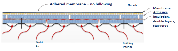 Figure #13 Adhered system where only the first layer of insulation is mechanically attached, significantly reduces interior air loss and thermal bridging. Image courtesy of GAF.
Systems that do not use fasteners, such as with the use of adhesives, greatly reduce thermal bridging by eliminating the path from the interior of the roofing assembly to the exterior. Adhering also prevents billowing of the membrane, by mitigating the interior air that can be brought into the roof assembly.
Asphaltic based membranes use asphalt to adhere the roof assembly. Modified bitumen roofs can be installed several different ways, including using a torch to melt the asphalt plies or by using a cold applied adhesive. The multiple asphalt plies form a robust roofing system that is not penetrable to air or the effects of billowing. Asphalt, and particularly hot (torched-applied) asphalt, can have strong fumes. On an occupied building where overburden would be placed as a retrofit, or a building in close proximity to other buildings, the use of asphalt may not be preferable since HVAC intakes may transport asphalt fumes into the building. Many insurance companies and jurisdictions do not allow the use of torches on the roof due to the fire hazard of open flames. Cold applied modified bitumen applications are an alternative that use an asphaltic based adhesive that is rolled onto the substrate prior to installation of the membrane. Cold applied applications offer the same modified bitumen wearing surface, but with fewer fumes than a traditional torch applied application. Modified bitumen roofs are excellent for mitigating air movement as the multiple layers are impermeable to air, and therefore are not subject to billowing like mechanically fastened single-ply systems.
Single-ply membranes tolerate a wide variety of attachment methods and are able to be both adhered and mechanically attached. The types of adhesives can vary from melted asphalt (with fleece-backed membranes) to various types of commercial adhesives manufactured for specific single-ply membrane types. Although product specific, single-ply adhesives release fewer hazardous fumes during installation, in contrast to those by asphalt based products. These adhesives do not require heating or torching for application and generally come in pails or canisters and can be installed with a roller or a spray attachment. Single-ply adhesives are generally less messy and can be quicker to install than traditional asphaltic based products.
Mechanical attachment of single-ply systems uses fasteners to install both the insulation layers and the membrane. The fasteners must be continuous through each layer and into the structural roof deck for securement. The number of fasteners will depend on project specific requirements, but typically for a mechanically attached system, there is a minimum of six fasteners per 4-foot-by-8-foot insulation board, and additional fasteners for membrane attachment, which can lead to a substantial number of fasteners penetrating and creating thermal bridges within the roof assembly. It is important to note that most systems require mechanical attachment of the first layer of insulation to be attached with fasteners, even if the specified system is to be adhered. However, by burying the fasteners in the system, and adding adhered layers of insulation and membrane on top of the mechanically attached insulation layer, the interior air loss and thermal bridging is significantly reduced.
Overburden systems installed over mechanically attached systems will billow and flutter with the roof membrane during high wind events. As the membrane flutters and moves, the overburden will shift on the membrane. Intensive vegetative systems may act as ballast and may inhibit the billowing. But for extensive vegetative systems and solar arrays, the overburden will likely move with the fluttering of the membrane. Over time, this could create additional stress on the overburden systems and their interface with the membrane, including abrading the membrane surface. The overburden systems may also experience stress and fatigue due to movement, which could decrease their overall service lives. Additionally, for solar arrays, as the membrane flutters, the movement of their associated electrical connections may compromise the energy performance. Similarly, for blue and purple roofs, the water catchment systems may be impacted by the billowing of the membrane. The catchment systems, likely designed to be rigid, may also experience fatigue due to the movement.
Therefore, an adhered roof membrane, such as those installed with the use of adhesives for both single-ply and modified bitumen systems, can contribute to a roof system lifespan and is a recommended installation method for overburden assemblies.
Insulation
Insulation is a critical part of any roofing assembly as it contributes to the overall energy efficiency of the building. The effectiveness of roof insulation is determined by its R-value, which is a measure of thermal resistance. The higher the R-value, expressed per inch, the better the thermal performance of the insulation and its effectiveness at maintaining interior temperatures. The most common roof insulation materials are polyiso, XPS, and EPS, each with different chemical compositions and material properties. Polyiso has the highest R-value at 5.7 per inch, followed by XPS with an R-value of 4.7 per inch and EPS with an R-value of 3.6 per inch. Higher R-value per inch means less material is required to achieve the desired insulating value. In overburden systems, the thickness of the overall installation can have an impact on the overall design of the overburden system. It is an industry standard for roof flashings to extend a minimum of 8 inches past the completed installation. For vegetative systems, this means that the flashing must extend 8 inches past the vegetation. Flashing heights are of particular importance at mechanical curbs and parapets. For a new construction installation, it is possible to raise the heights of the curbs and parapet walls to the desired height, however, in an existing building, this can be problematic.
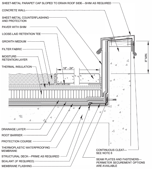 Figure #14 Flashing heights are recommended to terminate a minimum 8 inches above overburden height. Reference NRCA Detail VR-37, Low Parapet Flashing for Thermoplastic Waterproofing Membrane—Extensive (Shallow) Vegetative Roof Systems.
Another consideration for overburden systems is the location of the insulation. For typical assemblies, the insulation is between the membrane and the deck and therefore not exposed to UV, water, or chemicals. Polyiso, EPS, and XPS may all be used in standard roofing assemblies, however, in an IRMA assembly, there are additional considerations. In an IRMA assembly, the insulation will be covered by a filter fabric and then covered with the overburden, such as vegetation. The insulation will need to have low water absorption qualities as well as high compressive strength. XPS and EPS are suitable in IRMA applications.
Where the membrane is the outermost layer, layers of rigid insulation are typically installed directly on the structural deck, and the membrane is subsequently installed on the insulation. The orientation of the boards during installation can play a significant role in energy efficiency in the assembly. During installation, insulation boards should be installed so that the joints are staggered and offset, and several layers of insulation should be installed rather than just one thick layer. Any gaps between boards can decrease insulating ability by allowing thermal loss, an increased condensation potential if air travels into the roof assembly. Air often brings moisture, which if allowed to condense within the insulation, can saturate the insulation boards. Wet insulation has an R-value of approximately zero, which is like having no insulation at all.
Lightweight insulating concrete (LWIC) is an alternate type of insulation where EPS boards are encapsulated in a slurry coat of insulating concrete, then the membrane, and overburden would be placed on top of the LWIC. The R value of the system and overall thickness are tailored to each unique project. LWIC can be advantageous for use in overburden installations because a desired slope can be achieved with the LWIC system and it has a high compressive strength. There are also no gaps within the installation, such as between standard insulation boards, and fasteners are not required to attach the LWIC, so there is limited thermal and air loss within the system.
While perhaps the most important criteria is insulating ability, mitigation of air infiltration is equally important. When warm outside air meets with cold inside air, condensation can form within the roof assembly which can reduce the roof insulating value or cause microbial growth. Proper installation of the insulation is critical to mitigate heat and air flow. The insulation should be installed in a minimum of two layers, and the joints in the top layer should be offset from the joints in the underlying layer. The edges of adjacent boards should be in contact to limit gaps between boards. Air and heat that is able to travel between gaps in the board results in energy loss.
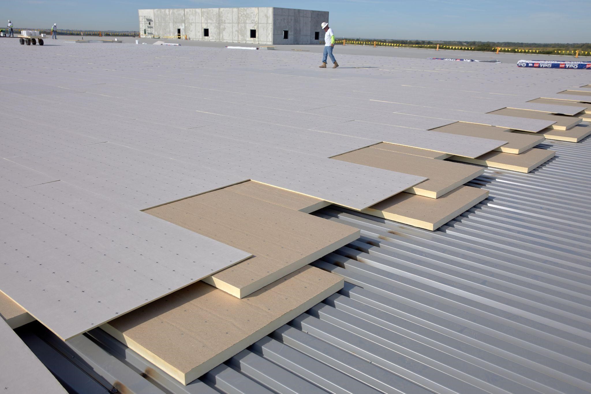 Staggered and offset insulation board joints. Photo courtesy of GAF.
Coverboards
Roof durability is system dependent and the entire roof assembly, including the inclusion of a coverboard, must be considered after selection of the overburden. Rooftops with overburden assemblies not only have more trades and increased foot traffic on the roof, but the overburden systems are an added dead load on the roof assembly. As with any roofing assembly, high traffic areas should be protected with walkway pads. Walkway pads, also sold in roll form, should be installed at roof access areas, such as hatches, around equipment, at overburden perimeters and locations where it may be accessed for service or maintenance. Walkway pads protect against abrasion and wear, but do not add compressive strength to the overall roofing system. The addition of a high-compressive-strength cover board below the roof membrane will enhance system protection, including compressive strength. Cover boards can help provide added protection against penetration by objects, including tools dropped by service contractors, wind-borne debris, and hail. Increasing the thickness of the cover board will increase its penetration resistance.
Typical coverboard materials are high-density polyiso insulation (HD polyiso) and gypsum. High-density polyiso is a high-density version of the traditional polyiso insulation. A ½-inch HD polyiso coverboard weighs 0.3 psf. The advantage of using HD polyiso is that it not only adds protection to the roof assembly, but it also adds an R value of 2.5 per half-inch. Typical gypsum coverboards, with an equivalent ½-inch board, weigh 2.76 psf and contribute an R-value of 0.5 per 1/2-inch.
Roof Installation Considerations (KW)
While the installation of overburden can contribute to sustainability goals of the building, ensuring a proper installation is critical to the long-term success of the roofing assembly. While the overburden itself can add to the energy savings and water retention of the building, the functionality of the roof is paramount. Tying in the overburden design to the overall roofing assembly design, down to the last detail, is critical. After the roof assembly and overburden has been decided, the roof details must be meticulously planned to include considerations for curbs, penetrations, flashings and review of the control layers to include water, thermal, air and vapor. The idea (and also code requirement) is that the control layers are continuous from the roof to the exterior walls. This prevents gaps in the system that can allow for water leaks or thermal breaks that may create locations of energy loss. Additional considerations to fire, wind and weight of the system must all be taken into account.
 Figure #15 Risk elements for blue and blue-green roofs. Image courtesy of Buildings.
Control Layers
Parapet and wall construction types for each unique construction require project specific detailing. While the main function of the roof is to prevent water intrusion, the roof can also play a role in energy efficiency. Continuous control of air, thermal, and vapor throughout the building enclosure can have profound impacts on the long-term performance of the assembly. A design professional should review each roof assembly to determine the individual components and details required for continuity.
The water control layer, which is the primary function of the roof, is controlled by the roof membrane. The roof membrane should be detailed so that it is continuous over the edge of the roof (inclusive of the parapet if there is one), and tied-into the water-resistive barrier behind the exterior cladding. Gaps in the water control layer can lead to leaks within the roof assembly as well as at the interior of the building.
According to the U.S. Energy Information Administration, approximately 18 percent of all energy consumed in the United States in 2020 was attributed to commercial buildings; according to research completed by Canada’s Building Efficiency Technology Access Centre, air leakage is responsible for approximately 15-35 percent of a building’s energy consumption. Air leakage, where associated with the roof, can lead to condensation within the roof assembly, interior drafts, or simply, loss of conditioned air. Independent of the overburden, air leakage from the roof is controlled by ensuring a continuous air barrier from the roof to the walls. Air leakage is often controlled by the roof membrane, which can function as an air barrier, however, ensuring the roof membrane is tied-into the exterior walls is a detail that is often overlooked. If a vapor retarder is included in the roof assembly, the vapor retarder typically functions as the air control layer.
Thermal bridging, as it relates to roof insulation, is where the insulation is interrupted and allows for heat loss within a building. A critical detailing location for thermal bridging occurs at the roof to wall edge or parapet wall interface. “In current IECC and ASHRAE 90.1 national model commercial energy codes, the basic prescriptive requirements for both walls and roof systems include the use of continuous insulation in many climate zones and construction types. Continuous insulation is more effective than parapet cavity insulation, which is tucked into the voids between framing members. In parapets, the framing members are exposed to exterior conditions on both sides of the wall, rendering cavity insulation highly ineffective. At the intersection of the roof edge and parapets, maintaining continuity of the "continuous insulation" can be difficult as it is often disrupted by wood blocking or structural elements.”27
The vapor control layer, while an important part of the assembly, is possibly the trickiest layer, since a dedicated vapor control, or a vapor retarder, is not always necessary within an assembly. While some scenarios, such as the presence of a concrete roof deck where a vapor retarder is recommended, in an assembly with a steel deck, the presence of a vapor retarder may cause moisture problems by trapping moisture within the roof assembly. Vapor transported moisture can result in condensation within the roof assembly. A hygrothermal analysis or dew point analysis is generally recommended to determine where the condensation point will occur in an assembly; the analysis will determine if a vapor retarder is required. As part of the analysis, it is important to determine the direction of vapor drive, which is from warm to cold. For a typical building, the direction of vapor drive may change throughout the year depending on interior and exterior temperatures. Condensation may occur only during certain times of the year or in certain conditions. It is important to note that roof membranes are generally impermeable to vapor, and in most cases, provide adequate defense against vapor intrusion. The presence of a vapor retarding roof membrane may be all that is required in most assemblies.
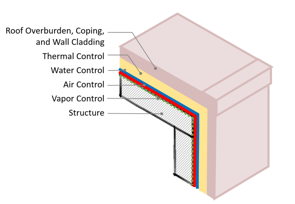 Figure #16 Simplified version of continuity of control layers from a roof to wall.
Overburden Layout, Details & Flashings
Qualified design and construction professionals must be integrally involved through the design and construction of both the roof and the overburden systems. The layout of the overburden should address access for initial overburden installation and both roof and overburden maintenance throughout the service lives of the components.
Adequate flashings and terminations of the roof membrane are arguably the most important part of any roof assembly. Inadequate detailing or termination heights leave the roof assembly vulnerable to water infiltration. Best practice dictates that the number of roof penetrations are kept to a minimum, which is not always possible. Maintaining flashing heights and detailing per manufacturer’s recommendations are crucial for a water-tight system. Inadequately detailed or flashed components may be water-tight for a period of time, but will most likely fail prematurely. Repairs can be costly at best, but removal of the overburden systems for the associated repairs can be an added difficulty and cost. In general, it is good practice to allow penetrations, flashings, expansion joints, drains, and other critical roofing interfaces to be accessible for maintenance and repairs.
For a typical roof assembly where the membrane is at the top of the assembly, NRCA recommends the height of the base flashing to be a minimum of 8 inches above the surface of the roof. For vegetative systems, the height of the base flashing should be a minimum of 8 inches above the surface of the growing medium. The use of couterflashings is recommended so that the base flashings are protected from UV exposure and physical damage. This is also best practice for limiting the scope of roof replacements. Flashings should be installed in accordance with current NRCA guidelines or the roof manufacturer’s construction details.
Movement of building elements should be anticipated and the placement of expansion joints at critical interfaces should be evaluated. In addition, the interaction between the overburden systems and the expansion joints must be explored. In general, it is recommended that the overburden systems do not cross or cover expansion joints.
While some roofing manufacturers do not exclude ponding on roof surfaces, it is a best practice to maximize drainage and remove ponding water within 24-48 hours. Ponding, solely as water, may not be detrimental to the roof’s surface, but ponding often holds debris, chemicals, and other deleterious substances, which can increase the rate of deterioration of the membrane. Ponding water also is also extremely heavy, and 1-inch of water can add 10 lbs/sf to the structural loading of the roof.
Overburden systems should be designed and installed so that they do not inhibit drainage of the roof. Particularly for solar arrays or tray vegetative roof systems covering large areas of the roof, drainage requires special consideration. Ballasted assemblies can block or inhibit drainage, which can result in trapped water on the roof membrane. The overburden layout design should also consider how the drains will be accessed for maintenance. Overburden systems that cover drains may allow for drainage, but may be near impossible to locate for maintenance and inspections. If possible, the layout should leave portions of the roof around drains open and unimpeded by the overburden.
Codes & Standards
The designer of record will determine which codes and standards will govern fire, wind, and structural considerations, generally starting with the International Building Code (IBC) and the referenced codes therein. In addition, the local Authority Having Jurisdiction (AHJ) should be consulted to determine the specific requirements for code compliance of the overburden systems.
Structural considerations for existing buildings during a retrofit scenario become extremely important, as the weight of each system must be analyzed. Solar panel weights vary from manufacturer (5 psf) and vegetative roof systems weight must be based on the saturated soil conditions, with extensive averaging 25 psf and intensive upwards of 100 psf. For blue with water retention, adding one-inch of water can add 10 psf to the roof dead loads, and purple-roof dead loads are the weight of the water plus the weight of the vegetation. Strengthening of existing structural building components may be difficult and expensive. For new buildings, the additional weight of the system can be taken into account with the original design, which offers the greatest potential for flexibility in design since the structure can initially be designed and installed to incorporate overburden.
Roof assembly wind design is mandated in IBC which references ASCE 7; roof wind uplift requirements will be based on individual building locations, wind speeds, building height, and other project specifics. However, there are no specific code or testing requirements for overburden on top of the roof. It is at the discretion of the overburden manufacturer’s (solar, vegetative, etc.) to determine whether their systems will withstand wind uplift for a particular location. As such, each individual manufacturer should be consulted during both the design and construction phase.
The International Fire Code (IFC) has provisions for Landscaped Roofs, Photovoltaic panels, and general roofing requirements. Requirements generally include clear paths to service equipment and other considerations to reduce roof fire hazards. It should be noted that the clear paths generally leave areas of the roof membrane exposed. Proper detailing of the exposed roof membrane should contain walkpads and protection as necessary to protect the membrane. The Landscaped Roofs provisions are located in Section 317 of the 2021 version of the IFC. The Code has provisions for maximum vegetative rooftop size (15,625 SF) and includes a maximum dimension of 125 feet for length or width and a clearance of 6 feet of listed Class A tested roof assembly between adjacent landscaped roof areas. A continuous border of 6 feet is also required around penthouses, solar panels, mechanical equipment, and other building service equipment to reduce fire hazards on the roof. Further guidance is provided for maintenance of the vegetation including irrigation and removal of dead foliage. The IFC has provisions for Solar, which is located in Section 1205 of the 2021 version of the Code. Solar photovoltaic systems require roof access, pathways, and spacing so that firefighters can access the roof. PV panels must allow a 6 foot perimeter pathway around the edges of the roof, and interior pathways must be provided at intervals not less than 150 feet throughout the length and width with additional requirements for standpipes and hatches.
Additional resources are available to include publications through NRCA (National Roofing Contractors Association), SMACNA (Sheet Metal and Air Conditioning Contractors’ National Association), ICC (International Code Council), ASCE (American Society of Civil Engineers) and ASTM (American Society for Testing and Materials).
Roof Systems Guarantees
The importance of matching the life expectancy of the roof and the overburden is critical since the cost of failure of the roof membrane can be high. Removal of the overburden is required for replacement of the roof assembly, which equates to loss of energy generation for solar arrays, potential expiration of vegetation, potential damage to aging solar arrays, and the added cost of overburden removal and storage during the process. In addition, at a minimum, the roof system must be designed such that the roof system guarantee will meet or exceed that of the overburden system.
Manufacturers typically do not guarantee overburden installations and the roof guarantee is only inclusive of the roof assembly. Therefore, most manufacturers specifically disclaim any liability arising out of or in connection with the integrity, installation or performance of, or damages sustained by or caused by the overburden systems.
Therefore the design of the roof assembly and the overburden, including NRCA and manufacturer's published specifications and details must be accepted by the manufacturer prior to overburden installation to avoid any lessening of coverage of the guarantee.
Case Study
Emma Park Neighborhood Center
Building Overview
Located in Butte, Mont., the Emma Park Neighborhood Center was built to accommodate programs to benefit poor and low-income households and serve as a social gathering place to help improve and rebuild the uptown area, which had fallen on hard times. The funding came largely from donations.
The ChallengeThe roofing work needed to begin in January 2014, which can be a challenge in Butte, as it’s 5,300 feet above sea level. In previous years, they had seen record temperatures hit as low as -52F degrees. Luckily that year, 75 percent of daytime temperatures were above freezing.
Roof & Overburden SystemThe roof incorporated a white reflective TPO membrane over polyiso insulation with each section having a different overburden system. One section of the roof contained a vegetative roof, one contained an amenity deck, and one contained solar panels.
 Emma Park Neighborhood Center TPO roof installed beneath vegetative roofing and solar panel installations. Photo courtesy of GAF.
Case Study
Mountain Resort Feuerberg Austria
Building Overview
The Feuerberg Resort in Austria is situated 1,769 meters above sea level, in the center of Carinthia, on top of the Gerlitzen mountain. The resort is located in close proximity to hiking trails and ski slopes and has on-site spas and pools.
The ChallengeDue to the alpine conditions, the requirements for the pitched and flat roofs of the facility are enormous. The hotel has not only to deal with extreme snow loads, but also has to withstand strong winds. The high wind suction forces create mechanical tensions in the roof structure. The resort wanted to incorporate vegetative roofing as several roof sections were in close proximity to pool and sunbathing areas.
Roof & Overburden SystemThe roof incorporated a modified bitumen membrane on the low-slope portions of the roof. Several of the roof sections contained extensive vegetative roof, including adjacent to the infinity pool in the photo below.
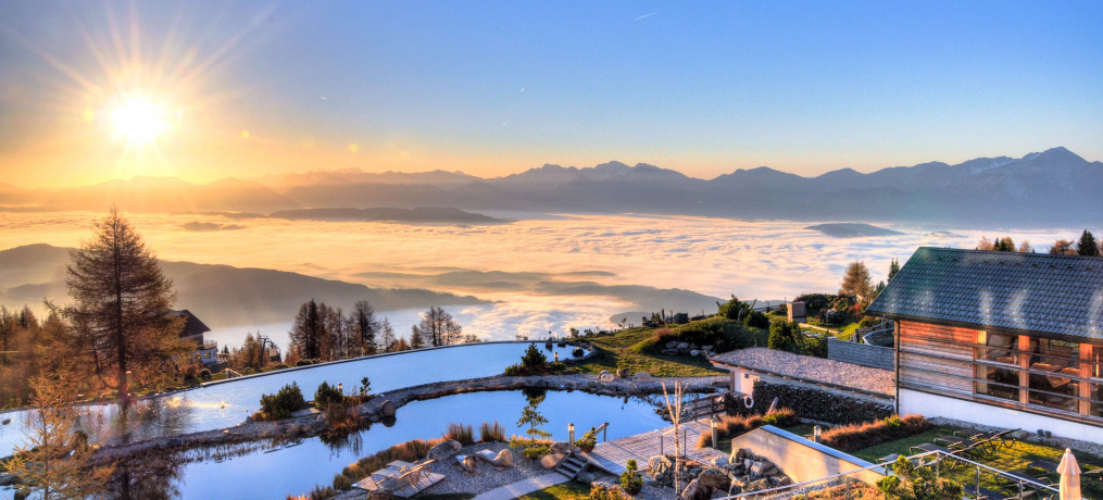 Mountain Resort Feuerberg Austria Modified bitumen roofing system installed beneath extensive vegetative roofing. Photo courtesy of BMI Group International.
Conclusion
While the roof is the primary defense to prevent water entering into a building, due to the current market trends and legislation, this previously underutilized asset is being recognized by owners for the opportunity the roof offers. Not only for sustainability goals and resiliency in an increasingly urbanized world in a warming climate; but, also for additional usable space. The variety of available overburden installations make sustainability accessible for a variety of buildings. Whether the goals are energy generation, water capture, or a place to sustain vegetation, many overburden choices are available. However, selection of the overburden assembly is only part of the design. The roof assembly itself can have a profound impact on the energy efficiency and operation of a facility. While its main objective is to mitigate water entry into the building, appropriate quantities of insulation, and air and vapor control can affect how the roof functions over time. In addition, appropriate selection of the entire assembly, including proper detailing and integration of the roof membrane, as well as installation are paramount to the overall success and longevity of the overburden system.
REFERENCES
1. Roofing Contractors Association of British Columbia. “Template: ROOFTOP EQUIPMENT & WALKWAYS (BUR).” Web. 4 April. 2022. https://rpm.rcabc.org/index.php/Template:ROOFTOP_EQUIPMENT_%26_WALKWAYS_(BUR)
2. Roofing Contractors Association of British Columbia. “Template: ROOFTOP EQUIPMENT & WALKWAYS (BUR).” Web. 4 April. 2022. https://rpm.rcabc.org/index.php/Template:ROOFTOP_EQUIPMENT_%26_WALKWAYS_(BUR)
3. Gray, Chris. “The Green Roofing Revolution”. Roofing Contractor. 24 January 2022. Web. 18 April 2022. https://www.roofingcontractor.com/articles/96502-the-green-roofing-revolution
4. SEIA. “US Solar Market Insight. Executive summary: 2021 Year in Review”. March 2022.
5. Resilient Design Institute. “What is Resilience?” Resilient Design. Web. 4 Feb. 2022. https://www.resilientdesign.org/defining-resilient-design/
6. Green Roofs for Healthy Cities. “About Green Roofs.” www.greenroofs.org. Web. 28 March 2022. https://greenroofs.org/about-green-roofs
7. Green Roofs for Healthy Cities. “About Green Roofs.” www.greenroofs.org. Web. 28 March 2022.
8. NJ.gov. New Jersey Stormwater Best Management Practices Manual. September 2017. Web. 18 April 2022. https://www.nj.gov/dep/stormwater/bmp_manual/Archived_NJ_SWBMP_9.08.pdf
9. NJ.gov. New Jersey Stormwater Best Management Practices Manual. September 2017. Web. 18 April 2022. https://www.nj.gov/dep/stormwater/bmp_manual/Archived_NJ_SWBMP_9.08.pdf
10. NJ.gov. New Jersey Stormwater Best Management Practices Manual. September 2017. Web. 18 April 2022. https://www.nj.gov/dep/stormwater/bmp_manual/Archived_NJ_SWBMP_9.08.pdf
11. NSF International. NSF P151: Certification of Rainwater Catchment System Components. Web. 18 April 2022. https://d2evkimvhatqav.cloudfront.net/documents/water_rainwater_catchment.pdf?v=1594930101
12. Livingroofs.org. “The blue green roof—helping cities cope with stormwater.” Web. 22 Feb. 2022. https://livingroofs.org/introduction-types-green-roof/blue-green-roof-cities-stormwater/
13. Andenæs et al. Performance of blue-green roofs in cold climates: A scoping review. Buildings. 2018.
14. Andenæs et al. “Risk Reduction Framework for Blue-Green Roofs”. Buildings. 26 April 2021. Web. 18 April 2022. https://doi.org/10.3390/buildings11050185
15. Shafique, M.; Kim, R.; Lee, D. “The potential of green-blue roof to manage storm water in urban areas”. “Natural Environmental Pollution Technology,” 2016.
16. Busker et al. “Blue-green roofs with forecast-based operation to reduce the impact of weather extremes”. “Journal of Environmental Management,” 1 Jan. 2022. Web. 18 April 22. https://www.sciencedirect.com/science/article/pii/S0301479721018120#bib4
17. SemperGreen USA. “Purple-Roof Case Study.” 12 Oct. 2021. Web. 22 Feb. 2022. https://www.sempergreen.com/en/sempergreen-academy/webinar-innovation-for-future-proof-cities
18. SemperGreen USA. “Purple-Roof Case Study.” 12 Oct. 2021. Web. 22 Feb. 2022. https://www.sempergreen.com/en/sempergreen-academy/webinar-innovation-for-future-proof-cities
19. Solar Energy Industries Association (SEIA). Solar Energy. Web. 18 April 2022. https://www.seia.org/initiatives/about-solar-energy
20. Solar Energy Industries Association (SEIA). Photovoltaics. Web. 18 April 2022. https://www.seia.org/initiatives/photovoltaics
21. Solar Energy Industries Association (SEIA). Photovoltaics. Web. 18 April 2022. https://www.seia.org/initiatives/photovoltaics
22. Pickerel, Kelly. “What are bifacial solar modules?”. Solar Power World. 2 April 2018. Web. 18 April 2022. https://www.solarpowerworldonline.com/2018/04/what-are-bifacial-solar-modules/
23. Oregon State University. “SUSTAINABLE FARM AGRIVOLTAIC”. Web. 28 March 2022. https://agsci.oregonstate.edu/newsroom/sustainable-farm-agrivoltaic
24. Biomimicry Institute. Web. 8 April 2022. https://biomimicry.org/janine-benyus/
25. Simon, Matt. “Your Rooftop Garden Could Be a Solar-Powered Working Farm”. WIRED. 3 Dec. 2021. Web. 8 April 2022. https://www.wired.com/story/your-rooftop-garden-could-be-a-solar-powered-working-farm/
26. Keegan, Jennifer. “CEU: Commercial Rooftop Solar Design Explained”. Building Enclosure. 2 November 2020. Web. 7 April 2022. https://www.buildingenclosureonline.com/articles/89371-ceu-commercial-rooftop-solar-design-explained
27. Meyer, Benjamin. “Parapets Part 1: Continuity of Control Layers”. 27 Sept. 2019. Web. 18 April 2022. https://www.gaf.com/en-us/blog/parapets-part-1-continuity-of-control-layers-281474980028103
Looking for a reprint of this article?
From high-res PDFs to custom plaques, order your copy today!
.webp?height=740&t=1767036885&width=auto "Header - BE 1170x658 (002).png")

.webp?height=740&t=1755781744&width=auto "KEE(2).png")