Sponsored by GAF
CEU: Low-Slope Roofing – Air Barriers and Vapor Retarders
Roof assemblies have more roles than simply keeping water out. Understanding control layers is key to successful design of modern roofs.
LEARNING OBJECTIVES
- Distinguish between the various control layers within roof assemblies, with particular attention to the control of air and moisture.
- Describe the reasons why air barriers and vapor retarders can be necessary and under what circumstances they are required.
- Identify which materials are appropriate for use.
- Recognize the pros and cons of the various choices that can be made for air barrier and vapor retarder placement within roof assemblies.
Complete the quiz and receive a certificate of completion
EARN: 1 AIA LU/HSW; 1 IIBEC CEH; 0.1 IACET CEU // AIA COURSE #BBE2021C
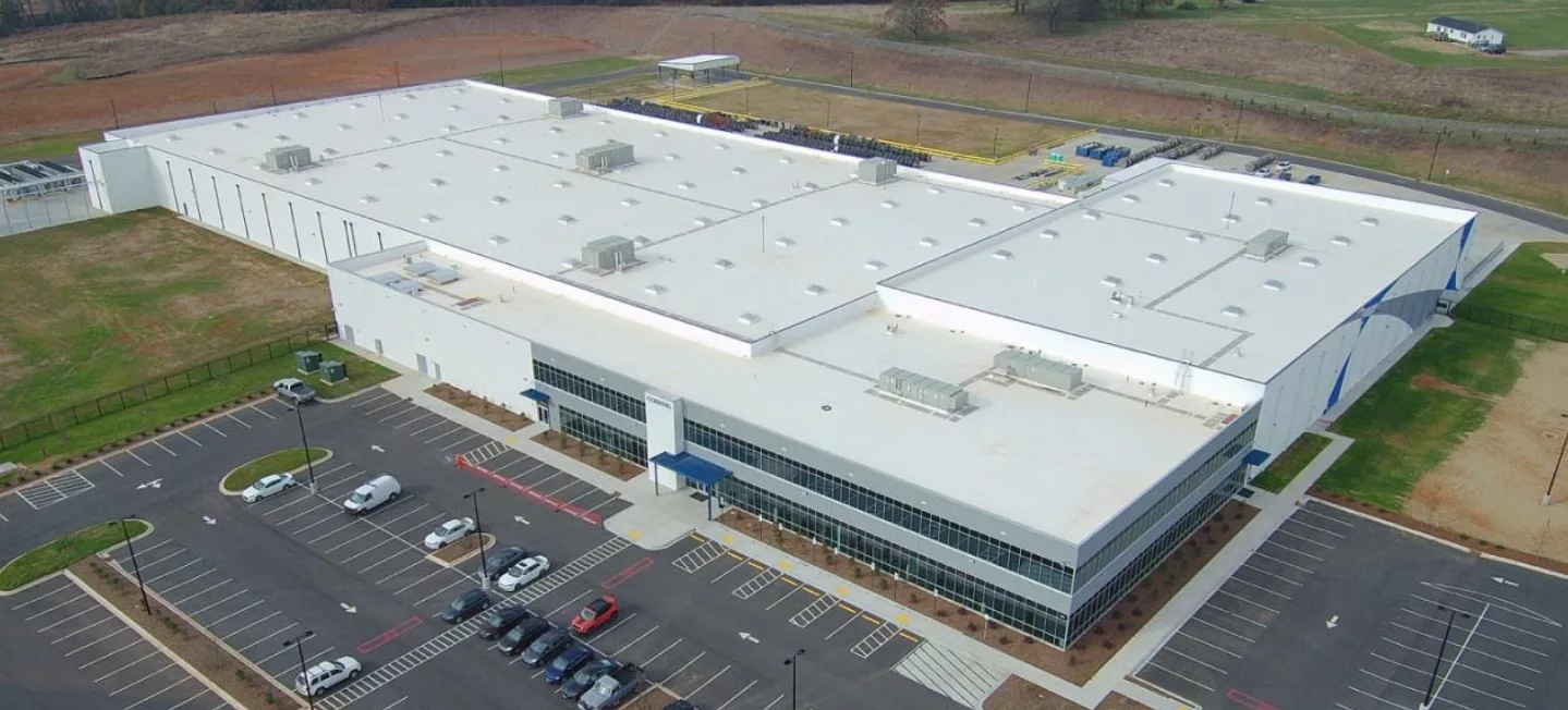
If we traveled back in time to the first dwellings humans constructed after they left natural shelters, we’d find that the role of the roof was to keep rain and other precipitation out. Caves and cliff overhangs were good at that, shelters made from vegetation such as grass and straw less so. Fast forward to the industrial revolution and you’ll notice that roofs became very good at controlling water ingress. At that time, shelters had evolved into dwellings and homes and a new type of building emerged – the workplace, whether factory, office, or warehouse.
As buildings have evolved, so have the requirements that have been placed on the building enclosure. No longer “just” a roof to keep precipitation out, today’s enclosure has many roles. Those roles are often carried out by different layers in the enclosure assemblies, whether they are roof, wall, or foundation. To help understand vapor retarders and air barriers, it helps to briefly review each layer’s role, beginning with the obvious and oldest before moving on to the recent air and vapor control roles.
- Water control – this is the obvious function of the building enclosure. Less obvious is the fact that for the wall of an enclosure, a 100% successful water barrier is considered to be unlikely. Hence the word “control”. Walls, with their many penetrations, plus doors and windows, are difficult to make entirely “waterproof”. Good wall designs accept the fact that some water ingress might occur and they have features that allow that water to drain down and then out of the structure.
- Structural control – every building enclosure assembly has structural elements, each supporting the others. In the case of a low-slope roof, the structural control is frequently supplied by the roof deck and any sub-structure beneath it. Structural support is not absolute and depends on snow loads, wind uplift pressures, expansion/contraction etc; hence the word “control”. As we’ll see, each layer of a roof assembly provides control over a property and is rarely absolute.
- Thermal control – going back to our description of the first dwellings, while preventing water ingress was a primary function of the first building enclosures, keeping occupants from freezing became an additional function. Today’s low-slope roof assemblies typically use an insulating foam such as polyiso. Good design is important so that the effects of thermal bridging and penetrations are taken into account.
- Air barrier – air leakage has been identified as a major impediment to achieving better energy efficiency of the building enclosure. Essentially, the goal is to prevent the loss of conditioned air from the interior to the exterior and the introduction of warm, humid air from the exterior to the interior. Just as thermal control needs to take into account thermal bridging and penetrations, so a material that blocks air is insufficient in and of itself. An air barrier, as we’ll see later, is an interconnected series of materials spanning the entire enclosure.
- Vapor retarder – for a variety of reasons, including the increasing air tightness of buildings and the use of air conditioning, it is ever more important to control moisture ingress into wall and roof assemblies. Importantly, control of moisture ingress from air leakage at assembly joints and vapor diffusion through materials can be achieved either through the use of layer material specifically designed for the purpose, or through careful installation of, for example, the thermal or air barrier control layer. All materials in a roof or wall assembly have some vapor retarding properties and the choice to include a specific vapor control layer should be considered along with the local climate, the building use, and the degree of assurance that vapor movement is retarded sufficiently.
- Other control layers – in some specific cases, other control layers can be added depending on requirements. For example, a cover board could be present to improve impact resistance. A cementitious or gypsum board might be added to improve fire ratings.
The Hypothetical “Complete Roof Assembly”
The hypothetical complete roof assembly is a conceptual design that shows each of the possible control layers described above and arranges them in an order that could be used as a starting point for many designs. In practice, not all will be needed and the order might change depending on material selection. Importantly, it assumes that each control layer is separate, which is not necessarily the case. The following schematic shows two possible such roof assemblies, one based on a steel deck and the other on a concrete deck.
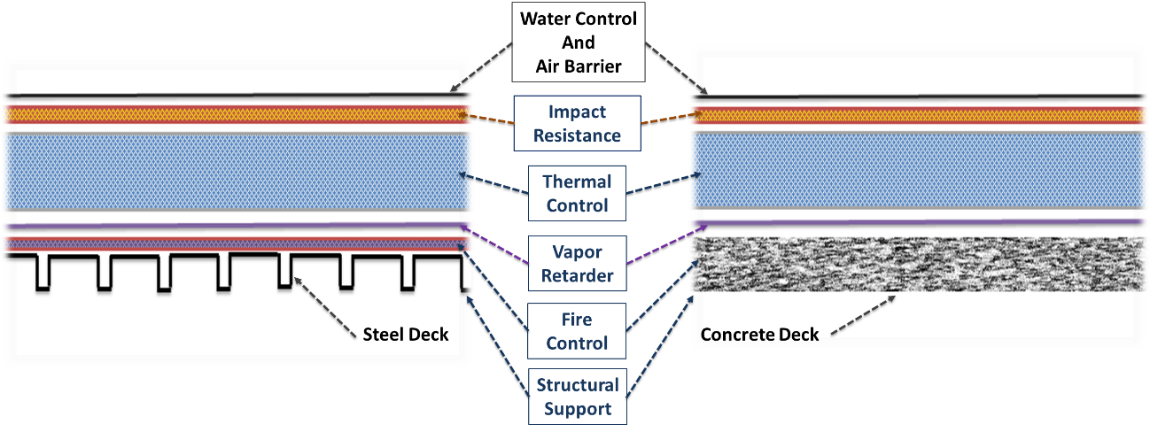
The hypothetical complete roof assembly schematic shouldn’t be used as an absolute design, but is a guide as to which control layers might be used. As stated earlier, some control layers might not be necessary and some might be combined. The important point is that it is useful to think about each possible control layer and then make decisions about which are needed, which can be combined, and so on. Also, the order of layers can be different, depending on building use, local climate, and other factors.
The schematic only shows the various layers within the field of the roof. However, very importantly, the order and sequencing of layers is strongly influenced by the edges. This means that how the roof is tied into or connected with the wall and its various control layers has a large influence on the order of the layers and which controls might be carried out by one layer. This is particularly the case when discussing air barriers and vapor retarders.
While the water and thermal control layers, i.e. the roof membrane and thermal insulation, are well understood, the use of air barriers and vapor retarders is still a source of confusion.
The use of air barriers and vapor retarders in construction is increasing rapidly, but many people from building designers through specifiers to installers remain confused as to the differences between them. There are many questions that frequently arise, such as:
- What is the difference between an air barrier and a vapor retarder?
- Is a vapor retarder the same thing as an air barrier?
- What have these materials got to do with roofing?
One problem with the entire topic is that there have been other terms used such as vapor barrier, air resistance layer, and moisture control layer. Are these related or different materials? Also, there can be confusion about what the roof designer or even the code requiring these materials is attempting to achieve or remedy.
Let’s begin with terminology; leading experts and trade associations such as the Air Barrier Association of America (ABAA) suggest using just these two terms: Air Barriers and Vapor Retarders. Each of those might have some variations that we’ll discuss later, but forget all the other terms and just use these two. It makes sense to start with air barriers and review why they are needed and where they can be placed.
Air Barriers
Why Are They Used?
It’s all about improving a building’s energy efficiency. Adding more insulation to a building enclosure has reached the point of rapidly diminishing returns. Also, insulation thicknesses are such that further increases would be difficult to accommodate without large increases in cost related to wall thickness or when reroofing for example. Air leakage has been identified as a significant impediment to further improvements in building energy efficiency. A building owner is paying to heat or cool the interior air, why allow significant loss of that conditioned air to the outside?
In 2012, the International Energy Conservation Code (IECC) published air barrier requirements, stating that “Continuous air barrier shall be provided throughout the building envelope with the exception of climate zones 1, 2, and 3.” The purpose of an air barrier is straightforward:
- Minimize the loss of conditioned air from within a building.
- Reduce energy loss – increase building energy efficiency.
So, what does this mean for the commercial low slope roof? Most people would assume that low slope roof membranes are automatically air barriers. However, that’s not the case and it’s very important to note that:
- The air barrier is a system of materials that controls air leakage / convective heat flow through the building enclosure from the interior to the exterior.
- The air barrier is not one material but instead is an integrated system of many different materials / components.
In the hypothetical complete roof assembly shown earlier, it would appear that the membrane is automatically going to be the air barrier. However, as noted, to be successful it must be tied into the material designated as the wall air barrier in such a way as to ensure there are no air leaks at the junction. Consider how a roof membrane often runs up and over a parapet wall. The building designer needs to specify that the membrane not just overlap the wall air barrier, but be flashed or sealed to it so that air cannot escape.
Air Movement and the Building Enclosure
The stack effect, in layman's terms, refers to the fact that warm air rises. In a tall narrow column, such as a skyscraper, this effect can be very pronounced. When warm air rises, it creates a higher pressure in the upper interior portion of a building. That increase in pressure also means the warm, moist air will escape through any pathways that are available. It will escape ‘into’ the roof or any air passage that goes to the exterior.
In addition to the increased air pressure due to temperature, there are several other factors that can lead to air being “driven” into roof assemblies:
- When doors, whether for people or for vehicles, are opened on the ground floor, outside air can enter to replace interior air that is being thermally driven to rise.
- Wind creates a negative pressure above a roof system and at higher velocities can lift a single-ply membrane between the rows of fasteners in the seams. This billowing membrane can pull interior air into the roof system regardless of temperature or moisture levels.
- Air conditioning and heating equipment force air through ductwork and into the interior of a building. By forcing conditioned air into a space, the space can become somewhat pressurized. Not to a great extent, but enough to create an imbalance between the interior and the exterior, forcing interior air into the roof assembly.
These effects are illustrated below:
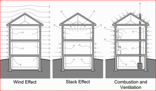 Figure 3: Processes that create air-flow across the building envelope. SOURCE: Building Science Digests, BSD-014: Air Flow Control in Buildings, John Straube, October 15, 2007
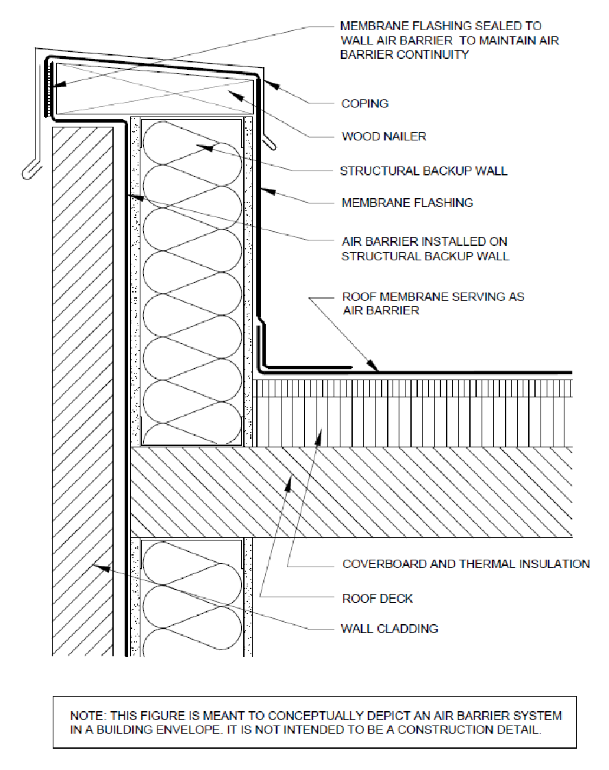
Roof to Wall Termination of Air Barriers
As described, to be designated as an air barrier, the roof material must be tied into the corresponding material in the wall. One example of how that can be achieved is shown here:
Another example, in a situation without a parapet wall is shown here:
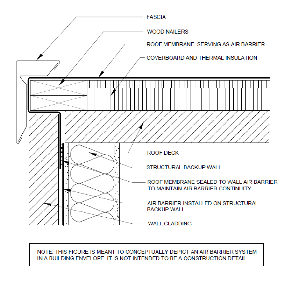
In each case, regardless of the situation, the designer needs to ensure that the air barrier is continuous around or within the building enclosure. All the materials designated to be part of the air barrier system must be securely connected and sealed to each other.
Air Barriers and Roof Penetrations
An air barrier’s effectiveness can be greatly reduced by openings and penetrations, even small ones. These openings can be caused by poor design, poor workmanship, damage by other trades, improper sealing and flashing, mechanical forces, aging and other forms of degradation.
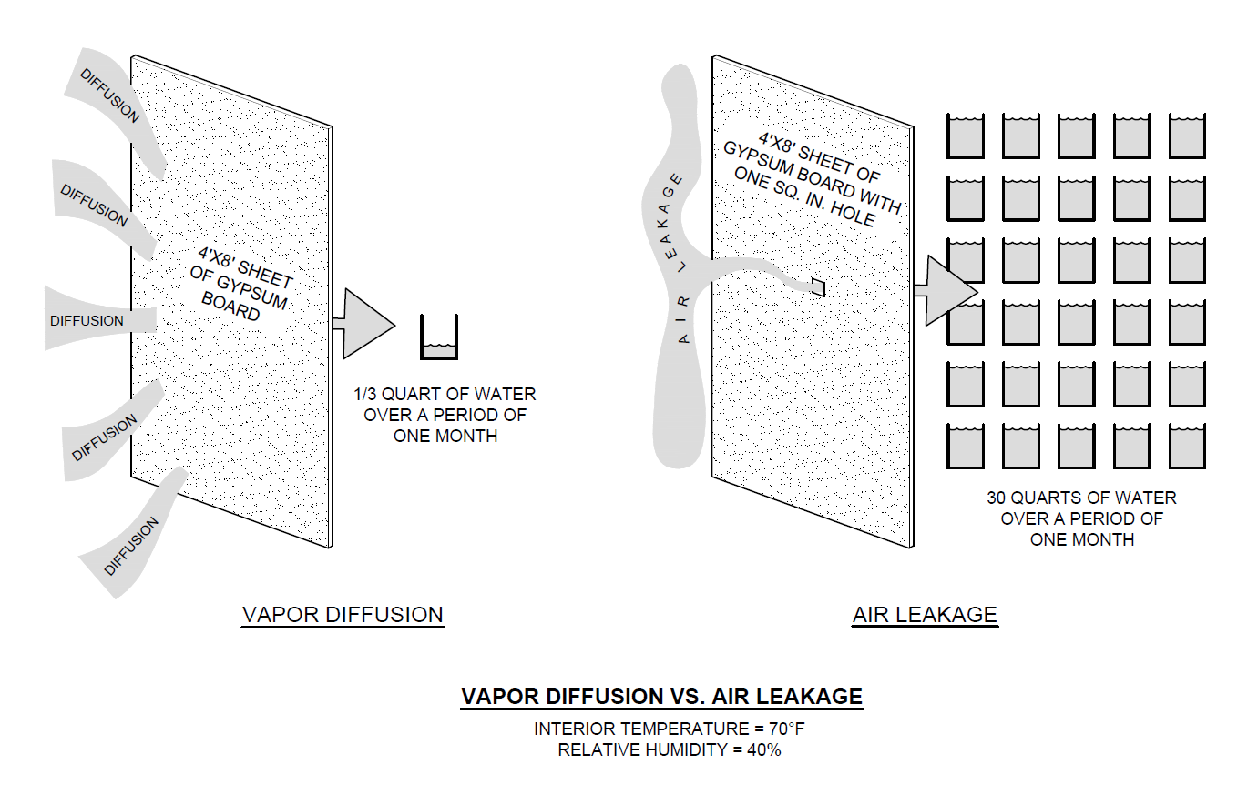
The National Research Council Canada collected research data that illustrated how even small openings can affect overall air leakage performance. For example, only about 1/3 of a quart of water will diffuse through a continuous 4 ft. by 8 ft. sheet of gypsum during a one-month period even though gypsum board has a very high permeance.
However, if there is a 1-square-inch hole in this same sheet of gypsum, about 30 quarts of water can pass through the opening as a result of air leakage. This relationship is illustrated in the figure below. The example illustrates that air leakage can cause more moisture-related problems than vapor diffusion.
As buildings become tighter, small air leaks can cause significant issues during winter months for buildings in the north. In such a case, a small leak can lead to significant condensation within the enclosure, leading to long term damage. An example of air leakage at a window to wall connection is indicated in the following infrared picture.

Can roof membranes always be part of an air barrier system?
Roof membranes that are automatically considered by Code to be suitable for use in an air barrier system are:
- Built-up roofing membrane.
- Modified bituminous roof membrane.
- Adhered single-ply roof membrane.
Single-ply membranes that are mechanically attached are also considered to be included so long as the manufacturer can provide a data certificate confirming that the material has an air permeability of no greater than 0.004 cfm/ft2 (0.02 L/s · m2) under a pressure differential of 0.3 inches water gauge (75 Pa) when tested in accordance with ASTM E 2178. In practice, most manufacturers have this readily available on request. But note that the IECC states an important caveat, that materials shall be deemed to comply provided joints are sealed and materials are installed as air barriers in accordance with the manufacturer’s instructions.
So, the answer is that, yes, properly installed roof membranes can be used as part of an air barrier system. To return to the concept of the complete roof, membranes can be considered as both the water and air control layer in a roof assembly.
Air Barrier Code Compliance
The roof membranes previously discussed can be part of an air barrier system and their use will be considered code compliant so long as they are correctly installed and tied into the wall air barrier layer. However, two additional means of achieving compliance are acceptable.
● Assemblies of materials and components (sealants, tapes, etc.) that have an average air leakage not to exceed 0.04 cfm/ft2 under a pressure differential of 0.3 in H2O (1.57 psf) when tested in accordance with ASTM E2357, ASTM E1677, ASTM E1680, or ASTM E283; The following assemblies meet these requirements:
o Concrete masonry walls that are
i. Fully grouted, or
ii. Painted to fill the pores.
● Whole building testing - air leakage rate of completed building can be tested and confirmed to be ≤ 0.40 cfm/ft2 at a pressure differential of 0.3 inches water per ASTM E779, ASTM E3158, or equivalent method approved by a code official.
When and Where Are Air Barriers Needed?
Designers should always consult local code to determine whether an air barrier is needed for a particular project. But, under the widely adopted IECC 2018 and ASHRAE 90.1 2016 state that a building enclosure is required to function as an air barrier for new construction except in climate zone 2b. However Chapter 1 Scope and Administration, Section 101.4.3 references additions, alterations, renovations or repairs. It reads as follows:
“Additions, alterations, renovations or repairs to an existing building, building system or portion thereof shall conform to the provisions of this code as they relate to new construction without requiring the unaltered portion(s) of the existing building or building system to comply with this code."
Section 101.4.3 also has a list of exceptions where compliance with the current code is not necessary provided the building's energy use is not increased. Exceptions 4 and 5 apply specifically to certain roof recovering situations:
“4. Construction where the existing roof, wall or floor cavity are not exposed.
5. Reroofing for roofs where neither the sheathing nor the insulation is exposed. Roofs without insulation in the cavity and where the sheathing or insulation is exposed during reroofing shall be insulated either above or below the sheathing.”
Exceptions 4 and 5 suggest the following:
● If a reroofing situation involves the tear-off of an existing roof system, i.e., exposing the roof deck and installing a new roof system, the new roof system will have to comply with the enclosure requirement of the current code.
● If a reroofing project involves a roof re-cover, i.e., the existing roof system remains in place, the new roof system does not have to comply with the current code, but can’t create a situation where the building will consume more energy as a result. Consider the following as an example where a roof recover could consume more energy than prior to recovering:
- The existing roof membrane is run up a parapet wall and tied into the wall air barrier on the exterior side, creating a continuous air barrier across the entire enclosure.
- The existing membrane is cut back to allow the new, recovering membrane to terminate on the inside of the parapet wall with a new term bar.
- The new, recovered membrane may now not be tied into the air barrier system for the rest of the building. This void in the air barrier system can lead to additional energy consumption and a new pathway for moisture laden air to condense within the wall or roof assembly.
For this example, it’s important (and may be required by code) to ensure the roof recovering maintains the continuity of the air barrier system after the new membrane is completed. It is recommended that designers discuss air barrier requirements with local code officials prior to reroofing projects.
Air Barriers and Parapet Walls
While many building designers successfully use the approach of extending the roof membrane up and over a parapet wall as shown earlier, with good sealing to the wall air barrier, this method can have issues. The space within a parapet wall has very little, if any, air circulation and can get very cold in northern climates during winter. Condensation could form which might then migrate downwards, potentially damaging the wall assembly.
While it’s not commonly done, one possible option that helps reduce condensation risks within parapets, is to continue the roof membrane down and under the parapet. Again, as with the first option, it must be securely joined to the wall air barrier. This alternative also requires a little more pre-planning and coordination across trades to make sure a stripped-in membrane is installed prior to the assembly of the parapet wall. The two approaches are shown conceptually below:
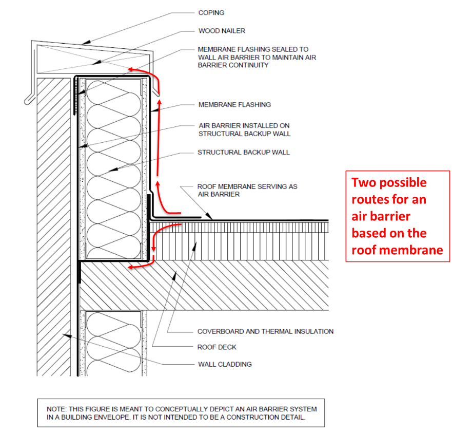
As will be shown later, an alternative approach is based on the use of a vapor retarder.
Tighter Buildings, but what about Indoor Air Quality?
As buildings get tighter, there can be concerns about indoor air quality. A detailed discussion on this topic is beyond the scope of this article, however there are at least two general approaches that are used. The first is to ensure that a commercial building’s HVAC system allows for sufficient fresh air to be drawn into the building. This task is usually assigned to the HVAC design engineer who follows standards such as ANSI/ASHRAE 62.1, Ventilation for Acceptable Indoor Air Quality, to determine how much make-up air to deliberately draw into the system.
Secondly, tighter buildings can have indoor air quality issues if the materials used to finish and furnish the interior off-gas odorous and potentially noxious chemicals. For that reason, many interior designers are selecting materials after careful review of Environmental Product Declarations (EPD), Health Product Declarations (HPD) and similar.
Air Barriers and the Construction Process
An air barrier is one of the few building systems that involves the coordination of many different trades. For successful installation of the air barrier each trade needs to understand which materials have been designated as being part of the air barrier. Before construction starts, a pre-construction meeting should occur with all parties involved with the design and installation of the air barrier system. Typically, this would include:
- General Contractor and air barrier, roofing, waterproofing, insulation, drywall, window, concrete, carpentry and masonry subcontractors.
- Building Owner or owner’s representative.
- Developer
- Architect
- Air Barrier Manufacturer
A pre-construction meeting is a good opportunity for the roofing contractor to be involved with the air barrier discussion which should include:
- Review of the drawings and specifications, especially the transition and tie-in areas.
- Review of the materials and accessories that covers which party is responsible for each material/system and any compatibility issues.
- Discussion of the sequencing of the work of all trades in order to determine a construction schedule.
- Discussion of coordinating an assembly mock-up, if required for the project
Vapor Retarders
Vapor retarders are commonly used in low-slope roof assemblies to perform two functions:
- Limiting airflow into the roof assembly. Minimizing the movement of air into the roof assembly, called air intrusion, reduces the movement of moisture-laden air in a building’s interior from moving into the roof assembly where condensation may be a risk.
- Reducing diffusion of moisture vapor through roof materials. Generally speaking, the risk would be higher when a building’s interior humidity conditions are expected to be relatively high, and/or the building is located in a cold climate. Additionally, vapor retarders can be used to help address moisture issues that can occur with structural concrete decks.
Locating the Vapor Retarder
To determine where a vapor retarder should be located, there are a number of steps that should be taken. Many on-line resources and guides to achieving this are available. However, in summary, the key steps are as follows:
- First, ensure that the design has limited the potential air intrusion, or air flow, into and out of the assembly being considered for condensation risk. Otherwise condensation from air flow has the potential to far exceed the amount of moisture from a steady-state calculation, such as a dewpoint or hygrothermal analysis.
- Determine the winter interior design dry bulb temperature. This design value is essentially the temperature that the building’s interior will be set at during the winter months. The information typically can be obtained from the HVAC system designer. However, for existing buildings, the building maintenance engineer is a possible resource.
- Obtain the winter exterior design dry bulb temperature. Design values can be found in Chapter 14—Climatic Design Information of the ASHRAE Handbook—Fundamentals; or in the Appendix of The NRCA Roofing Manual: Architectural Metal Flashing and Condensation and Air Leakage Control.
- Draw the roof assembly to a practical scale.
- Determine the roof assembly’s overall R-value and the values of the constituent components. Thermal properties of roofing materials can be obtained from manufacturers’ product literature. Other possible sources include: Chapter 26—Thermal Transmission Data of the ASHRAE Handbook—Fundamentals; or the Appendix of The NRCA Roofing Manual: Architectural Metal Flashing and Condensation and Air Leakage Control.
- Calculate the amount of heat loss occurring at the top surface of each material/layer. The temperature at the top of each material is lower as we move from interior to exterior. The heat loss formula for temperature drop (Td) is:
Td = Ti - [(R/RT) x ΔT]
where:
Td = temperature drop (temperature at top surface of material), degrees Fahrenheit
Ti = design inside (interior side) temperature, degrees Fahrenheit
ΔT = (winter interior design dry bulb temperature) - (exterior design dry bulb temperature)
R = cumulative R-values of materials
- Plot the temperatures at each material interface as shown in the following schematic:
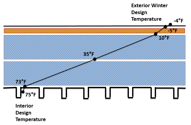
Note that in practice, for accuracy it is important to take into account the R-values of the air films above and below the assembly.
From the analysis, it should be clear that when specified, a vapor retarder would be placed at a location below the location of the dew point.
Material Selection Criteria
When selecting a vapor retarder material, it is important to consider the perm rating. This provides a measure of how much moisture can diffuse through the material. As will be discussed later, it can be important to ensure that some moisture transport is possible so that trapped moisture can escape. This could be from a small leak or from precipitation during construction. There are three classes of vapor retarder materials, as shown here:
Class Definition
I 0.1 perm or less
II Greater than 0.1 perm to less than 1.0 perm
III Greater than 1.0 perm to less than 10 perm
From a designer’s perspective, if a vapor retarder is needed, which class should be used? If a Class I vapor retarder is used, the concern is that any moisture (e.g., construction moisture due to installation methods, weather, etc.) that enters a roof system won’t be able to dry out. It’s often a good idea to select a vapor retarder that will allow some amount of drying from diffusion. Exceptions to this idea include roofs over indoor swimming pools and other high-humidity producing activities or processes. Another exception is a Class I vapor retarder should be installed over a new concrete deck to prevent the moisture in the concrete from drying into the roof system.
Vapor Retarders Material Types
In roof assemblies there are a number of choices of possible materials. Two categories of vapor retarders are worth singling out, bituminous and non-bituminous. Bituminous-based vapor retarders are the most common and include self-adhering modified bitumen sheets, and adhered smooth-surfaced APP or SBS-modified bitumen sheets. Additionally, there are built-up bituminous vapor retarders which are generally composed of one or two layers of asphalt felts or glass fiber mats applied with two or three moppings of hot asphalt.
Non-bituminous-based vapor retarders include plastic sheets, plastic laminates, kraft paper, kraft laminates and aluminum foil laminates. Some of these come with a self-adhering peel and stick backing and are generally self-sealing around fasteners. It is important to remember that vapor retarders, being installed lower down in a roof assembly, are frequently penetrated by fasteners from the insulation and membranes above. The adhesives used are designed to meet a self-seal test described in ASTM D1790.
There are non-bituminous types of vapor retarders that are installed loose-laid or adhered using a compatible adhesive to adhere the sheets to the roof deck or substrate. Black poly sheet, technically 6 mil polyethylene often referred to as Visqueen, is often used as a vapor retarder in residential crawl spaces. However, its use in roof systems is generally not recommended for several reasons:
- It does not self-seal around fasteners that penetrate through it. Vapor retarders are designed to meet a self-seal test described in ASTM D1970. Specifiers should always check that this is part of the material specification.
- Polyethylene is notoriously difficult to adhere to, which makes flashing and sealing around penetrations very difficult and unlikely to last.
- 6 mil polyethylene is essentially impermeable which means that any leak in the roof covering will let in water that can’t escape. Also, if some water has been present when the roof was closed up, from dew or light rain during the previous night, it will not be able to escape. Properly specified vapor retarders typically have some degree of permeability that will allow for migration of water from within a roof assembly downwards. The only exception to this would be for a building with a very high interior humidity or a concrete roof deck when it might be advisable to have a vapor retarder with essentially no permeability
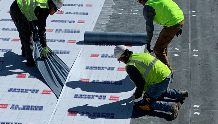
Installation of the Vapor Retarder
Using the complete roof assembly shown earlier as an example, any vapor retarder would be placed below the bottom layer of insulation. The analysis suggests that the dew point is somewhere within the bottom thermal insulation layer, meaning that condensation could possibly occur between insulation boards. Therefore, in this example, a vapor retarder would be placed directly over the deck. However, such a system may not have code approval as a roof system. So, many designs are based on installation of the vapor retarder over a cementitious or gypsum board attached over a steel deck. This is shown in progress below:
Is a Vapor Retarder Always Needed in Cold Climates?
Whether or not to add a vapor retarder to a roof assembly design is somewhat complex and can be a judgement call based on the designer’s experience. The designer should take into account factors such as:
- What is the building’s continuous air barrier strategy?
- The building’s intended use – for example interior swimming pools will add large amounts of moisture to the internal air and significantly raise the risk of condensation within the building enclosure. While this might be an obvious example, multi-family units can also have high humidity levels due to cooking etc. Some industrial operations (e.g., commercial laundromats) could also add large amounts of moisture to the interior air.
- The local climate and the designer’s experience – while some regions experience sub-freezing winter temperatures, some designers may have not seen condensation occurring when not using vapor retarders. Often a combination of the local climate, building use, and the roof assembly typically used can lead to quite low condensation risk. The impact of the overall roof assembly is discussed in the next section.
Do Vapor Retarders Have a Role in the South?
From the discussion so far, it could appear that vapor retarders are only considered for buildings in the north, i.e in climates that have cold winters. However, there is another situation where vapor retarders can be used in more southerly locations. Consider buildings with large footprints that have poured concrete floors. Warehouses and large retail developments would be examples. In some cases, the building is closed up before the poured concrete floor has dried. This allows other trades to commence work during construction but it can lead to very high interior humidity levels. It is not unusual for designers and developers of such buildings to include a vapor retarder in the roof assembly design. Once the floor has dried out, many months later, its role is minimal but it can prevent condensation and related damage during construction.
A Closer Look at the Vapor Control Layer
Returning to the concept of a complete roof introduced at the beginning of this article, using a vapor retarder is one of a few ways to control vapor and moisture movement from air intrusion. For buildings with a minimal risk of condensation, mechanically attached assemblies might be a viable approach. However, the following schematic shows some of the risks associated with such a design:
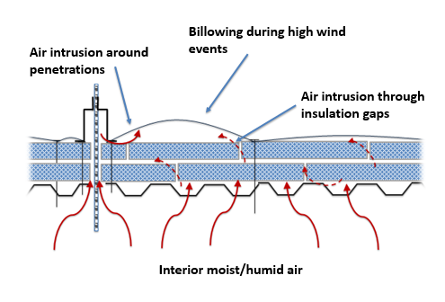
Even though the use of double layers of polyiso insulation with staggered joints, as first required by the 2018 IECC, limits the movement of air upwards through a roof assembly, it doesn’t prevent it. Also, penetrations that are not adequately sealed can allow for air movement. During high wind events, it is not uncommon to observe billowing of single-ply membranes installed in this way. The billowing actively draws interior air up into the assembly, which can result in the moisture carried with warm interior air condensing on the underside of the cold roof membrane.
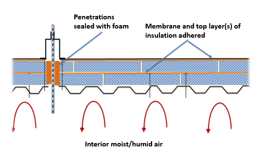
By adhering the membrane and top insulation layer(s) and sealing around penetrations, air flow can be significantly reduced.
This schematic might suggest that a vapor retarder isn’t ever required. However, there are limits to the success of this approach:
- While adhered systems do significantly limit the movement of humid air up into the roof assembly, there can be issues at the edges. Termination to the walls can be done more successfully with a vapor retarder as will be discussed later.
- Depending on the type of adhesive used and the installation quality, there can still be a condensation risk in buildings with higher levels of moisture.
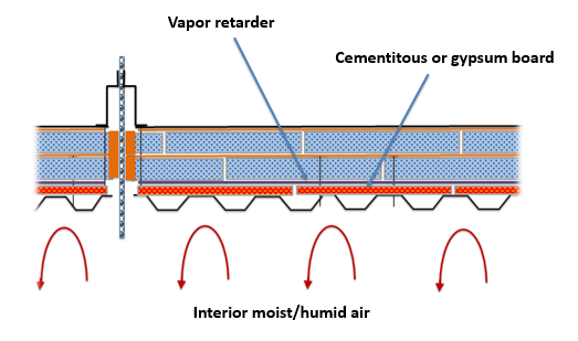
For those buildings and locations where moisture risks are high, the best approach is to install a vapor barrier. While it can be installed between insulation layers, a common practice is to first install a cementitious or gypsum board which acts as a substrate for a vapor retarder. This is shown in the following schematic.
Flashing and Termination of Vapor Retarders
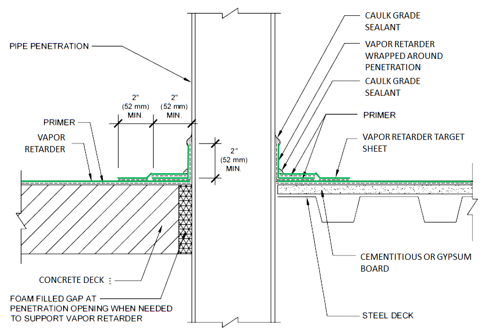
Vapor retarders should be treated like air barriers; they need to be continuously installed, sealed, and flashed around penetrations and terminated to wall systems such that interior air cannot migrate up into the roof assembly. Always consult the manufacturer’s recommendations for the specific vapor retarder being used. An example of how a vapor retarder is flashed to a pipe penetration is shown below:
Vapor Retarders and Structural Concrete Decks
A commonly used method to help address moisture issues in structural concrete decks is the use of a vapor retarder. Concrete roof decks that retain moisture continue to be a concern in the roofing industry. There have been changes in the materials and methods used in the construction of structural concrete decks over the past 30 years. Two significant changes to note are the use of lightweight aggregate in structural concrete and the use of non-removable forms. The use of lightweight aggregate that can hold more initial water than traditional “hard rock” aggregate, combined with the use of metal forms that are left in place, can increase the likelihood of the presence of moisture in the deck. And recent work indicates that even normal weight structural concrete poured over non-removable forms retains a significant amount of water within the concrete.
The use of a vapor retarder to restrain movement of moisture from the deck into the roofing system is a commonly used method. Allowing concrete to thoroughly dry is most appropriate; however, it is reasonably impractical. In addition, precipitation during construction can add more water to a concrete deck making drying more difficult to achieve. It is common to install a vapor retarder on the top surface of a concrete deck. The Midwest Roofing Contractors Association, MRCA, is advising that a vapor retarder of less than 0.01 perm is necessary over new concrete roof decks. From a practical standpoint, a vapor retarder of less than 0.01 perm is effectively a vapor barrier—almost no moisture passes through. As shown earlier, a Class I vapor retarder has a rating of 0.1 perm or less.
Why are Air Barriers and Vapor Retarders Sometimes Confused?
As discussed earlier, air barriers are required to prevent the loss of conditioned air from within a building. Using the concept of a complete roof assembly, it is important to have an air control layer that is as complete and unbroken throughout the building enclosure. The materials that are part of that control layer should stop air movement and all tie together so that leaks are minimized.
When penetrations and transitions are detailed vapor retarders also block air flow and it is this fact that can cause some confusion. However unlike for example, roof membranes, vapor retarders are frequently materials that can have some limited permeability. As discussed earlier, this can help minimize risks associated with trapped water.
Since vapor retarders block air movement, they can be used as the air control layer within a roof assembly.
The designation of the roof membrane as part of the air control layer (i.e. air barrier) requires that it be terminated correctly to the wall air barrier. As discussed earlier, this is important for the various trades to understand during construction. However, it could be that the vapor retarder be designated as the air control layer. It would therefore serve two functions; air and vapor control. Again, to be successful, it should be tied into the wall air barrier. Two approaches to controlling air flow were shown earlier.
Summary
When considering air barriers and/or vapor retarders, it can be beneficial to think in terms of control layers. It is important to determine which layers within the roof assembly are being designated as control layers for air and for moisture.
- Air barriers are often code required. They are a system of interconnected materials that must be sealed together. The roof material that has been designated as the air barrier must be terminated and sealed to the air barrier layer within the wall assembly.
- The simplest approach for the roof designer is to designate the roof membrane as the air barrier and carry it up and over a parapet wall or over the edge if a parapet wall is absent. Once overlapping the wall, it must be terminated and sealed to the wall air barrier material so that air and moisture leaks are prevented.
- While more complex to design and install, it may be prudent to have the air control layer extend through the base of a parapet to the wall. At that point it must be terminated and sealed correctly to the wall air barrier. This approach minimizes air flow into the parapet and lowers the risk of condensation within the parapet.
- Vapor retarders are used within roofing assemblies to control moisture migration. They also block air flow providing that they are tightly sealed around penetrations and the perimeter.
- If the risk of condensation is deemed to be reasonably low, two layers of insulation with staggered joints might provide for sufficient vapor control against air intrusion.
- At higher levels of risk, condensation mitigation from air intrusion could be achieved by adhering the upper layer(s) of insulation and the membrane.
- For buildings with significant risk of condensation issues, a vapor retarder should be installed below the dew point. It is important to ensure that air intrusion is first minimized and any vapor retarder installed is self-sealing so that insulation and membrane fasteners, if used, don’t degrade the performance.
- Because vapor retarders block air, they can be used as both the vapor and air control layer. However, such an approach should be used with care since it is dependent on careful design and installation.
- To be successful, the designated air and vapor control layers must be understood by everyone involved in the installation and construction. Pre-construction meetings that review the control layers are essential.
Moving Forward
Roof system design is always the responsibility of the designer, but perhaps the designers in the roofing industry can find some takeaways from the wall industry. There is always more to learn and understand about the building science of our roof systems.
Looking for a reprint of this article?
From high-res PDFs to custom plaques, order your copy today!
.webp?height=740&t=1767036885&width=auto "Header - BE 1170x658 (002).png")

.webp?height=740&t=1755781744&width=auto "KEE(2).png")


