Navigating Fenestration U-Factors
Properly Calculating Fenestration U-Factors is Important to Building Enclosure Design

The building code provides requirements for energy performance of window and other fenestration assemblies, including the maximum allowable fenestration U-factors. It can be challenging for designers to meet the U-factor requirements, when working on new and existing buildings. Understanding the energy code requirements and how to properly calculate the fenestration U-factors is an important skill to develop to inform the building-enclosure design. This article provides a review of fenestration U-factors, related code requirements, an example calculation, and other practical considerations for understanding U-factors.
What is a Fenestration U-Factor
The International Energy Conservation Code (IECC, 2018 referenced herein) defines U-factor (thermal transmittance) as “the coefficient of heat transmission (air to air) through a building component or assembly, equal to the time rate of heat flow per unit area and unit temperature difference between the warm side and cold side air films [(Btu/h • ft2 • °F) [W/(m2 • K)].” In other words, a U-factor defines the rate of heat loss through a component or assembly. U-factor is the reciprocal R-value, so a lower U-factor means greater resistance to heat flow and improved thermal performance.
Fenestration U-factor ratings are generally determined in accordance with National Fenestration Rating Council (NFRC) 100 “Procedure for Determining Fenestration Product U-factors.” NFRC 100 requires computer simulations to determine the U-factor of fenestration products. It requires physical testing to validate baseline product simulations, when baseline product simulations cannot be validated (simulated and tested U-factors for the baseline product are not equivalent), or when simulations cannot be performed in accordance with the standard. Simulations and physical testing exclude perimeter conditions to limit heat transfer to the fenestration product only. Therefore, designed and constructed perimeter conditions, such as the position of the fenestration thermal break relative to exterior building wall insulation plane, some perimeter flanges, and other elements that create thermal bridges, can significantly affect in-situ fenestration-perimeter interface thermal performance.
Reporting of Fenestration U-Factors
Fenestration manufacturers often report the total product U-factors (combined frame and glazing) based on different glazing options (glazing U-factors). The reported total product U-factor is typically based on NFRC standard model (specimen) size, which varies by product type (e.g., curtain wall is different than a casement window). The model size impacts performance, as discussed in more detail below.
Insulating glass unit (IGU) manufacturers report the overall, center-of-glass (COG), and
edge-of-glass (EOG) U-factors for the IGU. The overall IGU U-factor can be determined using the EOG and COG values and will be affected by the IGU make-up, including spacer type, IGU gas fill type, coatings, overall thickness, etc.
Fenestration product size affects performance. For example, a larger glass/aluminum curtain wall/window wall/storefront/sloped glazing (one NFRC 100 product type) assembly with an IGU can have a notably lower total product U-factor (i.e., improved thermal performance) compared to the same assembly that is smaller. This is because the IGU EOG and fenestration framing generally exhibit higher heat transfer (i.e., lower thermal performance) compared to the IGU COG. Therefore, as the percent glazing area of the fenestration decreases, the U-factor of the assembly generally increases. The NFRC standard model size for a storefront product type is 78.75 inches by 78.75 inches with one intermediate vertical mullion, which is a relatively large fenestration. This means the actual size used on many projects may be smaller or include more intermediate framing than the NFRC standard model size and have a higher U-factor (i.e., lower thermal performance) than reported by the manufacturer.
Many fenestration product manufacturers only report the total product U-factor for the NFRC standard model size. However, fenestration manufacturers typically can provide charts, when requested, to compare the COG U-factor against the project-specific percent vision area to determine the total product U-factor for sizes other than the NFRC standard model size.
Energy Code Requirements for Fenestration U-factors
The IECC generally governs building-energy-performance requirements, which can be further amended by the local authority having jurisdiction. The IECC provides fenestration U-factor requirements and allows the use of prescriptive and performance compliance methods. Using the prescriptive method to determine fenestration U-factor compliance means that the designer must confirm that the U-factor for each fenestration assembly is equal to or less than the prescribed maximum value, with a few exceptions. The performance compliance method provides for a more holistic whole-building energy analysis, though some jurisdictions require maximum U-factors for assemblies even when incorporating a whole-building analysis.
The design of new buildings or additions often utilize the performance compliance method. Even with the performance compliance method, designers may still check basis-of-design fenestration U-factors against prescriptive requirements early in the design process. This cursory check allows the designer to evaluate the anticipated performance of the schematic design, particularly in jurisdictions, where codes require minimum overall building-enclosure performance. If issues are identified during this process, the designer can modify the design to meet performance requirements.
The design of fenestration replacement in existing buildings often utilizes the prescriptive compliance method. Meeting fenestration U-factor requirements using the prescriptive method can be more challenging, particularly when replacing fenestrations in older buildings that were not designed with modern energy performance requirements in mind, and where opening sizes and fenestration appearance likely cannot be easily modified.
The IECC (subsection C401.2.1) recognizes this challenge by allowing the use of an area-weighted average to meet prescriptive requirements for replacement fenestration products; application of this method is beyond the scope of this article. When applying the prescriptive code to replacement products, the designer is generally required to consider operable and fixed windows and entrance doors separately because each product category has different U-factor requirements. Spandrel areas are sometimes considered part of the opaque wall area.
Calculating Fenestration U-factors
The size and configuration of a specific fenestration assembly will affect its total product U-factor. Therefore, a designer must calculate the total product U-factor based on the specific fenestration assembly to determine energy code compliance and not simply use a published U-factor for the NFRC standard model size and configuration that is most likely different. Spandrel areas and vision areas should be considered separately within a product assembly.
As an example, we use an aluminum-framed glass/aluminum window (storefront product) to illustrate how to calculate a total product U-factor for an assembly that does not exactly match the NFRC standard model size. The NFRC standard model size and configuration for this product type is approximately 78.75 inches by 78.75 inches with two lites with one intermediate vertical mullion, as shown in Figure 1a. Figure 1b shows the configuration and information for the example assembly, which includes two vision lites (IGUs with COG U-0.24) with one intermediate horizontal mullion. The published total product U-factor for the NFRC standard model size is U-0.35 with a COG U-0.24 (COG U-factors will vary but this could represent a 1-inch gas-filled IGU with low-e coating). The steps to determine the actual total product U-factor for the example assembly are described below:
Step 1: Determine the percent vision area, which is also the percent daylight opening (DLO). The percent vision area for the example is approximately 83 percent.
Total Vision Area=Height of DLO x Width of DLO
(DLO is the glazing infill dimension measured from the glazing sightline. It does not include framing dimensions.)
Total Area=Window Unit Height x Window Unit Width
(Includes framing dimensions. If there are multiple units stacked together, divide the dimension of the framing between the two units that share the mullion in half. Some curtain wall assembly NFRC U-factors may be based on the centerline of perimeter framing if continuous curtain wall is assumed)
Percent Vision Area=100 x (Total Vision Area)/(Total Area)
Step 2: Determine the COG U-factor for the desired glazing from published manufacturer’s data. The COG U-factor for this example is U-0.24.
Step 3: Use a chart similar to Figure 2 to determine the actual total product U-factor. The total product U-factor for the example assembly is U-0.42; recall that the U-factor for the NFRC standard model size is U-0.35. In this same example, removing the intermediate horizontal mullion increases the percent vision area (85 percent) and reduces the U-factor to approximately U-0.39. Designers often have to request information similar to the chart shown in Figure 2 from fenestration manufacturers because this information is not always available on their web sites.
If spandrel glazing is included in a fenestration calculation, it must be analyzed separately from the vision glazing. The calculation is similar to vision glazing, except that spandrel R-value (from insulation within the spandrel) and percent spandrel area are calculated. Where mullions are shared between adjacent units (such as between spandrel and vision units), the influence of half of the frame width should be applied to each unit in the calculation. For configurations that include a mixture of different units (i.e., spandrel and vision, operable and fixed, etc.), the total assembly U-factor can be determined by calculating the area-weighted average of the U-factors.
The example illustrates that calculating actual fenestration total product U-factor is important. Designers should not simply use the manufacturer reported U-factor because it is typically reporting the U-factor for NFRC standard model size, and the project-specific fenestration size and assembly typically has a different total product U-factor. Design may be an iterative process to meet energy code requirements, particularly for fenestration replacement projects. It may be necessary to look at multiple fenestration systems and components (e.g., fenestration type, pressure plate material, IGU spacer type, IGU cavity gas fill and thickness, etc.). Operable vents, spandrel conditions, etc. can increase the complexity of the calculation, but it is still a relatively straightforward hand calculation in many instances.
Conclusions
Understanding fenestration U-factor (thermal transmittance), energy code requirements, and how to properly calculate project-specific total product fenestration U-factors for are important to inform a project design. We suggest considering the following, when evaluating U-factor performance of fenestration products on a project:
- The total product U-factor of a fenestration assembly will vary based on its size, intermediate framing components, and glazing. The actual total product U-factor for the project-specific fenestration will likely be different than the NFRC standard model product U-factor reported by the manufacturer.
- Consider code requirements for the project-specific jurisdiction. Consider how the project will meet energy code requirements (prescriptive, performance energy model, etc.). Determine basis-of-design fenestration products and geometries early in the design process, to understand potential challenges with meeting code U-factor requirements.
- Fenestration replacement for existing buildings can present challenges to the designer with respect to matching existing fenestration opening sizes and minimizing aesthetic changes to the existing building. The building code recognizes these constraints and allows designers to use an area-weighted average to meet the prescriptive requirements for replacement fenestration products.
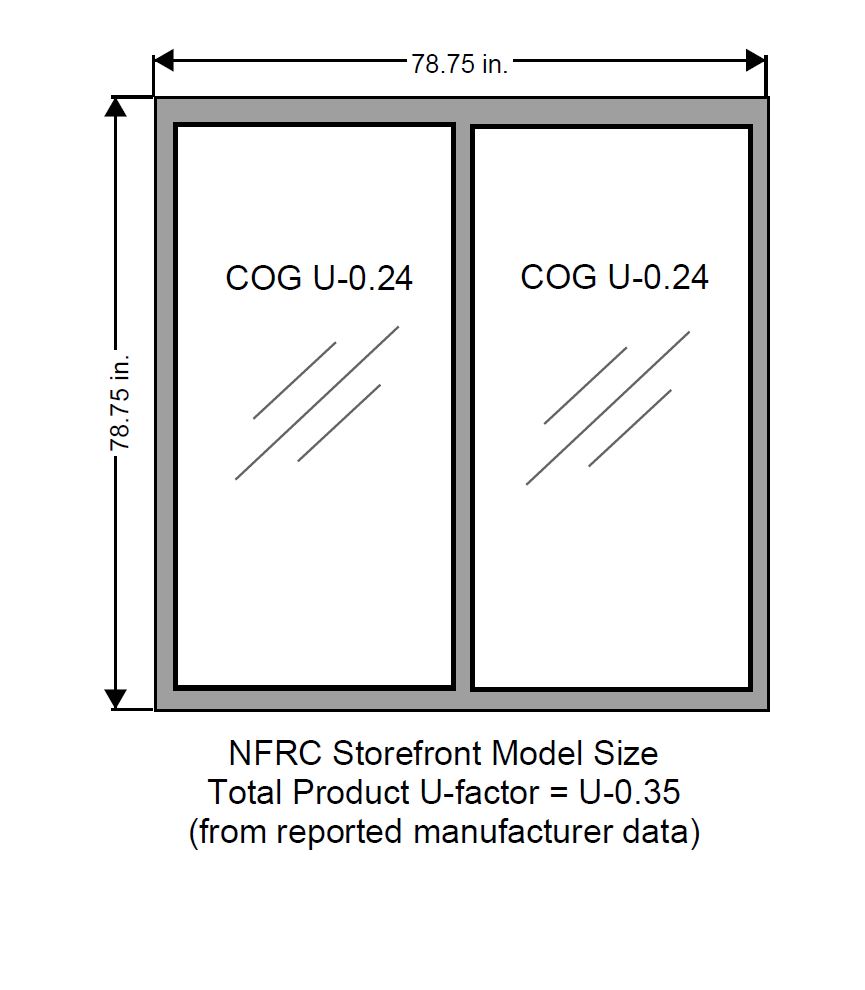
Figure 1a – NFRC standard model size and configuration for a storefront unit.
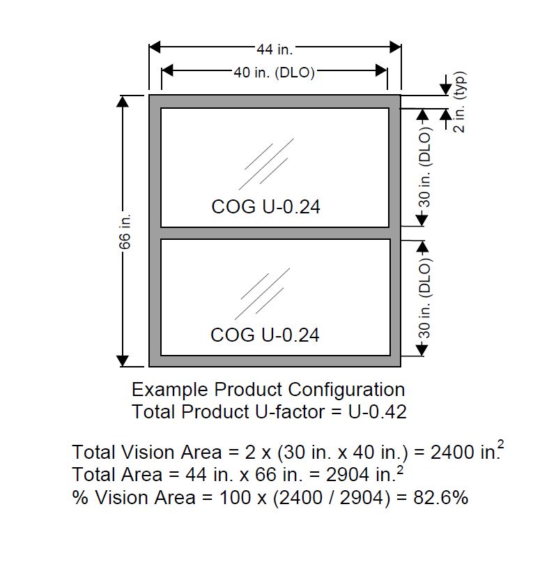
Figure 1b – Example storefront product size and configuration.
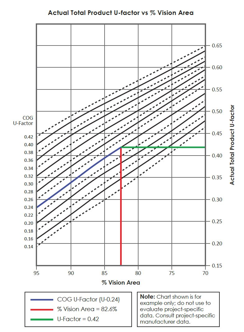
Figure 2 – Example of charts that may be published by manufacturers to determine actual total product U-factor based on percent vision area and COG U-factor.
Looking for a reprint of this article?
From high-res PDFs to custom plaques, order your copy today!
.webp?height=740&t=1767036885&width=auto "Header - BE 1170x658 (002).png")

.webp?height=740&t=1755781744&width=auto "KEE(2).png")
.webp?height=200&t=1759756834&width=200 "Kingspan(16).png")