Stud Wall Design with Polyiso and New Wall Calculators
Speculation shrouds the future: traditional sources of energy are recognized to have environmental drawbacks, while alternative sources have a long way to go before they can be considered viable replacements. In this uncertain time, energy efficiency of the building envelope ought to be a top priority in new construction to reduce heating and cooling demands.
For stud frame walls, there are two keys to energy efficiency: insulation and moisture control. The need for insulation is obvious; slowing the transfer of heat lessens the need for a building’s HVAC systems to run. However, moisture control is just as important. If water is allowed to accumulate or condense, the structure will begin to degrade, and no amount of insulation will save a rotting wall.
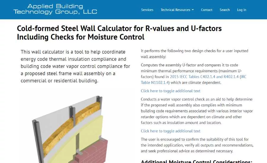
Clearly, an efficient wall must also be a resilient wall. Nevertheless, specifying a code-compliant wall for both optimal thermal and moisture performance can be a challenge. Two online tools (one new, one previously existing) are ready to help the designer simplify this process. The Steel Wall Calculator and the Wood Wall Calculator developed by the Applied Building Technology Group (ABTG) check a given wall for thermal and moisture code compliance, and allow the user to fine-tune a design for cost and industry best practice. At first glance, the calculators can seem a little overwhelming, so this article will walk the reader through their use to clear up any confusion. Additionally, we will examine how the use of polyisocyanurate (polyiso) insulation can ease the complications of wall design.
Once used primarily on roofs, polyiso also works well throughout the building envelope. In this article, we’ll focus on its use in walls.
One of the greatest threats to the integrity of an insulation system is the effect of thermal bridging. Thermal bridging occurs when there are paths that heat can take through a wall that avoid whatever insulation has been installed. For example, in a stud wall with insulated cavities, heat can travel through the studs themselves rather than the insulation—the studs act as thermal bridges.
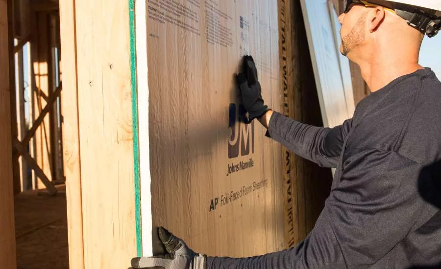
When lumber studs are used, they can degrade wall thermal performance by 19 percent when compared to the rated R-value of the cavity insulation.1 Steel studs are much worse, causing a drop in performance of as much as 47 percent.2 This is where polyiso comes in. Polyiso is installed as continuous insulation (CI) outside of the studs in an unbroken layer to block the thermal bridges provided by the studs. There are several products marketed for use as CI, but polyiso stands out for having a high R-value.
When properly taped, sealed and integrated with flashing, foil-faced polyiso can serve as a water resistive barrier (WRB) and air barrier. The example below highlights the advantages of these traits.
Getting to Know the Calculators
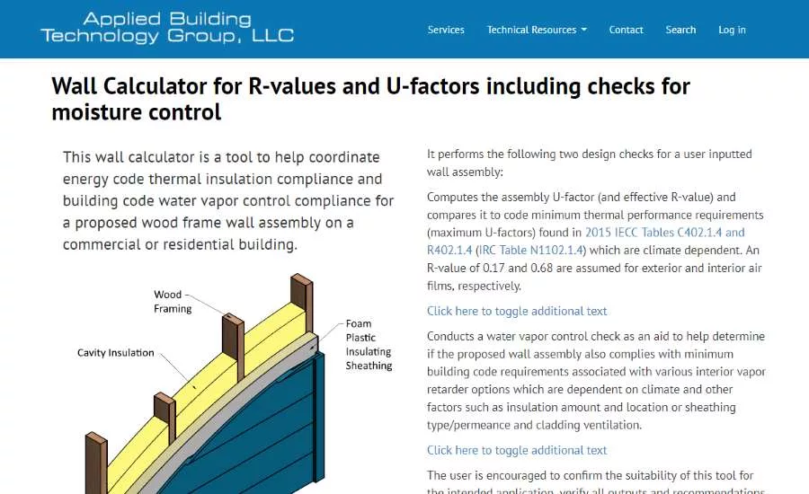
First, consider the calculators. The user interfaces for both calculators are on display in Figures 3 and Figure 4.
They are organized in a similar fashion, with the top section containing explanatory information, and the input/output section below (input is on the left and output appears on the right). The main visual difference is that the wood calculator includes an optional input section for a net permeance calculation
Input
Under Wall Assembly Inputs, the user is asked to supply the applicable building and energy code, the climate zone where the wall will be built, and specific details about the makeup of the wall including cladding type, interior and exterior sheathing layers (if included), stud size and spacing, and of course, continuous and cavity insulation R-values. These inputs are used to check thermal and moisture properties of the wall against the code requirements and building science best practices.
Output
On the right, the first section of output compares the calculated assembly U-factor with the energy code requirement. It also compares the prescriptive insulation requirements to the user-proposed insulation levels. If either of these comparisons pass, the wall is considered code compliant for thermal purposes. If both checks fail, the user can increase the insulation amounts in either the CI input or the cavity insulation input until one of the checks passes. By altering the amounts of cavity and CI, the user can compare the relative performance of several configurations, and possibly save on material costs. Note that obtaining higher R-values is more efficiently achieved by adding more continuous insulation due to the reduced thermal bridging.
Below the thermal check is the moisture check. This section computes the ratio of CI to cavity insulation, and, based on the result, makes a recommendation regarding the use of class I, II or III vapor retarders on the interior side of the wall. These recommendations are based on both the U.S. and Canadian codes, as well as independent research (a full treatment of the relevant building science can be found in a research report from ABTG). Following these recommendations will help to ensure that the wall cavity stays dry, and any moisture that does make it inside is able to dry to the interior or exterior, rather than being trapped between two low permeance material layers.3
Example
Now armed with some basic knowledge, the best way to understand the calculators it to use them. We will design a steel stud wall for a commercial nonresidential building in Chicago.
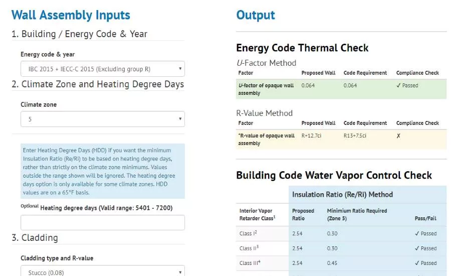
- Chicago is located in climate zone 5 according to the International Energy Conservation Code (IECC). In the input section of the steel calculator, select “IBC 2015 + IECC-C (Excluding group R)” under Building Code and Year, and select “5” under climate zone.
- To the right, in the Energy Code Thermal Check under “Output,” the U-factor and R-value requirements for the wall have updated to reflect the climate zone 5 requirements (at this point, the calculator allows the user to use the heating degree days at the specific location of the project to interpolate the moisture requirements, but we will leave this field blank and use the default value).
- Inputs three through eight each describe some aspect of the wall’s construction. We will use the default values for cladding, exterior sheathing, stud and framing factor, and interior sheathing, which leaves us with the insulation.
- There are several options. We could follow the prescriptive requirement: R13 + 5CI, or we could choose our own CI and cavity insulation levels, testing different values to find a combination that works. One option would be to rely entirely on polyiso CI, and leave out cavity insulation entirely. Through trial and error, we find that CI rated R-12.7 satisfies the energy code (Figure 5). The water vapor control check indicates that any class vapor retarder can be installed on the interior due to the high insulation ratio.
The thickness of polyiso CI insulation required to meet the R-12.7 requirement will vary based on the exact product selected. Remember, the high R-value of polyiso CI will require less insulation to meet the same R-value requirement compared to other options. Equally important, most manufacturers supply polyiso in various thicknesses that can be selected to fit the needs of your job. No insulation is needed in the cavities, which simplifies construction labor.
Additionally, relying entirely on polyiso CI results in a wall cavity that stays at the same temperature as the conditioned space year-round. This ensures that condensation within the cavity will be kept to a minimum, so the builder has the flexibility to use any class vapor retarder on the interior of the wall without the risk of trapping moisture. As noted earlier, polyiso CI can serve as WRB and air barrier, eliminating the need for multiple other layers to the wall assembly.
Behind the Scenes
You may be asking yourself, “how do the calculators generate their results?” Due to the large difference between the thermal conductivities of wood and steel, the two calculators use different methods to arrive at a wall assembly U-factor.
- The wood calculator uses the parallel path method described in the ASHRAE Handbook of Fundamentals, chapter 27.4
- The steel calculator utilizes the correction-factor approach from the International Energy Conservation Code (IECC)5 commercial provisions.
The parallel path method assumes that heat flows in straight paths parallel to one another and perpendicular to the surface of the wall, without moving “sideways,” say, from cavity insulation to stud. If this assumption is true, then, the R-value of each path can be computed, and combined to get an assembly U-factor. For current purposes, heat can take two paths through the wall: through the cavity, or through the stud. The R-value of each path is found by totaling the R-value of each layer in the path. Then, the two paths are area-weighted to yield an assembly R-value and U-factor. For studs at 16 inches-on-center spacing, the calculator assumes the wall is 25 percent framing and 75 percent cavity. As the spacing increases to 19.2 or 24 inches, the framing percentage drops to 23.8 and 22 percent, respectively.
The parallel path method cannot be used for a steel framed wall, however. The central assumption—that heat only flows in parallel paths normal to the surface of the wall—does not hold true for steel studs due to the complexity of the stud shape and its thermal conductance. Instead, heat in the vicinity of the stud will flow towards the stud and the less-restrictive pathway it provides. For steel-framed walls, other methods must be used. The correction factor method is one such alternative, which downgrades cavity insulation in steel stud walls by a correction factor determined through testing. The wall assembly R-value is simply the sum of the R-values of each continuous wall layer (cladding, sheathing, finish and CI) and the corrected cavity insulation value. The correction factors for a variety of wall configurations are given in Table C402.1.4.1 of the IECC.
Conclusion
In the complex process of specifying robust walls to meet code requirements, the wall calculators from ABTG can speed up decision making via making iterations easier and with less guesswork. This opens up opportunities to be more creative with respect to making assemblies easy to install while maximizing energy efficiency and economy. Polyiso CI simplifies design and construction, providing an all-in-one control layer for stud walls. More information about polyiso is available at polyiso.org, the website of the Polyisocyanurate Insulation Manufacturers Association (PIMA). Many other resources regarding the use of CI can also be found at continuousinsulation.org.
- Results from parallel path R-value calculation for SPF 2x4 studs at 16 inches-on-center with R-13 cavity batt insulation.
- Results from correction factor R-value calculation for 3.5-inch steel studs at 16-inches-on-center with R-13 cavity batt insulation.
- Note: the wood calculator includes a second moisture check. If the user prefers, he or she can choose an interior vapor retarder based on the permeance of the exterior layers. Once the permeance of each individual exterior layer is entered in the optional input area on the left, the calculator will display usage recommendations for each class of interior vapor retarder. This alternate check is absent from the steel calculator due to the fact that most steel wall assemblies include class I equivalent vapor retarders on the exterior side of the wall due to CI requirements, and this precludes the permeance based approach.
- https://www.slideshare.net/virginiavenus/2009-ashrae-handbookfundamentalsinchpoundeditionashrae2009.
- https://up.codes/viewer/colorado/iecc-2015.
Looking for a reprint of this article?
From high-res PDFs to custom plaques, order your copy today!
.webp?height=740&t=1767036885&width=auto "Header - BE 1170x658 (002).png")

.webp?height=740&t=1755781744&width=auto "KEE(2).png")


