CEU: Envelope-Based Solutions for Metal Buildings
Building with metal can offer many financial incentives for architects and owners, however understanding how to navigate the increasingly restrictive industry standards and requirements requires knowledge, patience and the right tools.
Building with metal can offer many financial incentives for architects and owners, however understanding how to navigate the increasingly restrictive industry standards and requirements requires knowledge, patience and the right tools.
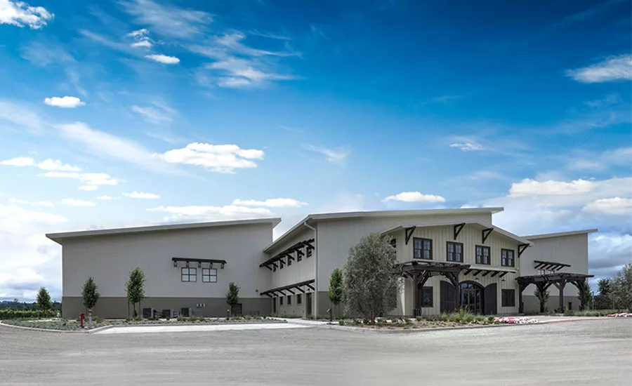
The winery is a mixed-use facility that includes office space, a tasting room, a crush pad area, a fermentation room and spacious barrel storage. This project consists of a custom-engineered metal building system and IMPs.
The winery is a mixed-use facility that includes office space, a tasting room, a crush pad area, a fermentation room and spacious barrel storage. This project consists of a custom-engineered metal building system and IMPs.
ASHRAE 90.1-2013/IECC 2015 sets goals as a 15 percent improvement over current 2010/2012 code with full insulation, air infiltration improvements, daylighting required and increased HVAC efficiency. ASHRAE 90.1-2025 IECC 2027 set net-zero as the goal, with alternative energy sources and supporting green energy.
After reading this article, you should be able to...
- Describe the impact to commercial metal building enclosures of impending code changes, including IECC 2015, ASHRAE 90.1-2013 and ASHRAE 90.1-2016, which is in review.
- Explain the different obstacles and options for code compliance, including various insulation systems.
- Detail how the use of COMcheck, U.S. Department of Energy software, helps to maintain cost effectiveness of value-engineering metal building enclosures.
- Identify emerging trends in energy use reduction and overall impact on building design.
To complete the quiz and receive a certificate of completion, follow this link: http://bit.ly/BESUMMER2017D
Energy use in U.S. buildings, comprising nearly five million commercial buildings and 115 million residential households, represents 40 percent of U.S. energy consumption. Building energy codes are a critical component of the national effort to control the increasing impacts of building energy use. The Department of Energy supports and participates in the development of these codes, which have over the last several years become more stringent, more complicated and more highly enforced across the country.
ASHRAE 90.1, the IECC and other building energy codes, standards, guidelines and rules are adopted as part of the larger body of building codes, and must be satisfied as a condition for approval to construct and occupy buildings. This article will discuss the impact of more stringent and closely regulated building energy standards and codes on the building process—specifically, as they affect the envelope for metal buildings. We will consider some of the challenges in adhering to the codes, and we also will identify solutions and compliance tools, products and resources that help projects meet code requirements and gain the associated energy benefits.
The Impact of Newer Code Adoption and Enforcement
Building energy codes and standards establish minimum efficiency requirements, assuring reductions in energy use and emissions over a building’s life cycle. These energy codes are a subset of broader building codes, which establish requirements and govern building construction. While building to code has its challenges, the positive result is buildings that provide greater comfort and are more cost-effective to operate long-term.
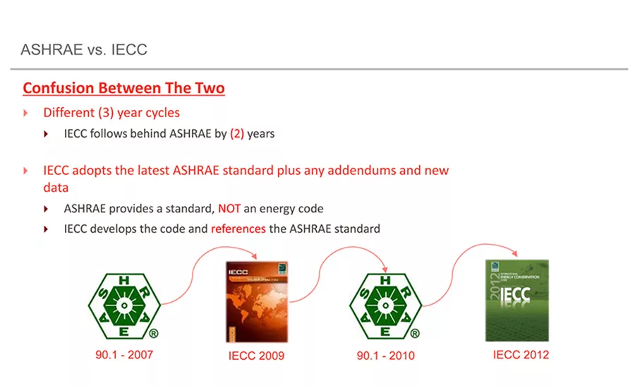
When people speak in general about Building Energy Codes, they often are referring to American Society of Heating, Refrigerating and Air Conditioning Engineers (ASHRAE) 90.1, a standard, the International Energy Conservation Code (IECC), a code, or to state and locally adopted codes based on ASHRAE 90.1 and IECC. The IECC applies to both residential and commercial buildings; ASHRAE 90.1 applies only to commercial buildings (including multi-family high-rise buildings).
The ASHRAE 90.1 standard is updated every three years. The IECC is generated two years after the ASHRAE 90.1 standard and incorporates new information and addenda from ASHRAE 90.1. The U.S. Department of Energy supports and participates in the development of both. Once the IECC or ASHRAE 90.1 is updated, states and other jurisdictions can decide whether to adopt the newer version.
The energy code landscape in this country is complicated. States may adopt the IECC or ASHRAE 90.1 with or without amendments, or a state may implement its own energy code, as California and Washington do. In addition, cities and counties may adopt “stretch codes” that are more stringent than the statewide code. In the several “home rule” states, cities and counties may adopt their own codes, which may or may not be the same as the statewide code. As a result, the energy code landscape for a single state may be a patchwork of older and newer codes.
It’s critically important to check with your local building official to understand which code to follow. Just because a state has adopted a new code does not mean that all counties and jurisdictions are enforcing it.
The Impact of Energy Codes
The most recent three editions of the IECC and ASHRAE 90.1 have the potential to generate almost a 30 percent reduction in energy use compared to codes a decade ago. These codes represent a significant savings opportunity for U.S. home and business owners.
Model energy codes for residential and commercial buildings are projected to save (cumulative 2010-2040):
- $126 billion energy cost savings
- 841 MMT of avoided CO2 emissions
- 12.82 quads of primary energy
These savings equate to the annual emissions of:
- 177 million passenger vehicles
- 245 coal power plants
- 89 million homes
For perspective, the primary energy consumption of the entire U.S. commercial and residential sectors in 2015 was estimated at 38 quads.
The most recent versions of IECC and ASHRAE 90.1 are IECC 2015 and ASHRAE 90.1-2016, although these versions are not currently enforced or referenced uniformly across the U.S. As of October 2016, nine states have adopted IECC 2015 or ASHRAE 90.1-2013 or have an equivalent state energy code. Sixteen states are following IECC 2012, and another 18 are following IECC 2009. The trend for states has been to wait two code cycles before making a change; in other words, a state that is currently following the IECC 2009 is likely to adopt IECC 2015, rather than IECC 2012. This change to a significantly more stringent code can catch even seasoned building professionals off guard, as solutions relied on for years may no longer be adequate.
Some states and/or jurisdictions accept either the IECC or ASHRAE 90.1 as the compliance path; however, it is up to the system designer to make this determination. In addition, if your state or jurisdiction allows you to follow either the IECC or ASHRAE 90.1, you must choose one or the other for all building elements; for example, you cannot “mix and match” by using ASHRAE 90.1 for the envelope and IECC for mechanical and lighting.
In previous iterations, ASHRAE 90.1 has been a less stringent, more forgiving path for compliance, and in some cases, it can be more economical. It is worth noting that ASHRAE 90.1 distinguishes between heated buildings and semi-heated buildings, and allows lower insulation requirements for the latter. Many architects automatically spec IECC without realizing they can use ASHRAE 90.1 as a compliance path. Understanding which options are available for code compliance could potentially save projects both time and money.
There are a number of challenges around code adoption, enforcement and compliance, which can lead to confusion for building professionals:
- In many states, local jurisdictions can choose whether or not to adopt or enforce the state code. Implementation, compliance and enforcement vary with different jurisdictions which may lead to confusion as to which code is in effect.
- There is an unmet need for understanding new code requirements and language as well as appropriate construction techniques, materials and technologies.
- Enforcement issues are connected to both lack of training and lack of manpower (understaffing). Training is often unavailable or inadequate, despite its importance to all stakeholders, including designers, builders and those overseeing code compliance. The time-consuming nature of plan review and inspections isn’t always accounted for in department staffing.
- Some codes that were adopted some time ago are seeing more widespread enforcement. For example, the updated California Title 24, which technically went into effect in July of 2014, is now being more vigorously enforced.
These challenges highlight the need to educate building professionals. If you haven’t yet seen the impact of newer, more stringent codes in your state, you likely will see them in the near future.
Energy Codes and Building Envelope
Energy codes are divided into three major categories: building envelope, HVAC and lighting. For this discussion, we are primarily concerned with the building envelope—specifically, opaque roof and wall assemblies. Codes specify insulation levels for metal building floors, ceilings, roofs and walls, and include requirements for protecting and sealing a building against air leakage and moisture migration. The Climate Zone in which a building is located has an impact on envelope requirements. IECC and ASHRAE 90.1 envelope tables are sorted by climate zone. In general, the higher or colder the climate zone, the more stringent the requirements.
Appendix A of ASHRAE 90.1 includes tables (Metal Building Insulation Tables A2.3 and A3.2) that depict the minimum R-values for insulation and maximum U-factors for the entire assembly of different generic assemblies—for example, a standing seam metal roof with a single layer of insulation and thermal spacers.
U-factors have come into play during the last few code cycles. Rather than considering individual components, the U-factor measures the thermal conductivity of the entire assembly, taking into consideration framing, fasteners, spacing of framing and fasteners, and whether insulation is compressed or fully expanded. The U-factor is the inverse of the R-value; consequently, a lower U-factor indicates better performance.
Considering an entire assembly with the U-factor method allows an architect or designer to specify an assembly that is not described explicitly, if it has a U-factor equal or less than that specified in the tables. We will re-visit this concept in the section on compliance.
The Impact of Stricter Energy Codes
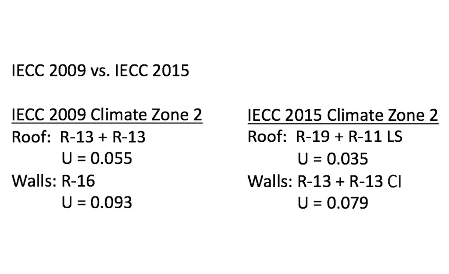
To understand the effect of more stringent code requirements, let’s look at a specific example comparing IECC 2009 and IECC 2015 prescriptive requirements for insulation for roof and walls in Climate Zone 2. In general, older codes allow a single or double layer of fiberglass insulation compressed over the purlins. Experienced builders have been accustomed to installing single-layer roof and wall systems to meet code and could consider anything other than single-layer applications “overkill.”
But newer codes require higher R-values (and lower U-factors). For example, IECC 2009 first introduced the requirement of continuous insulation (CI) in metal building wall assemblies for climate zones 5-8. IECC 2015 calls for CI in metal building wall assemblies and higher performing roof assemblies across all climate zones.
Going back to our specific example, IECC 2015 requires significantly higher total R-values than IECC 2009 (R-19 and R-11 versus R-13 + R-13, respectively). In addition, IECC 2015 specifies the use of a liner system (LS). A liner system consists of a continuous membrane installed below the purlins, uninterrupted by framing members. Unfaced insulation sits on top of the membrane and between the purlins. Thermal spacers must be used with this assembly, unless the U-factor method is employed.
For walls, IECC 2009 simply requires R-16, usually fiberglass insulation, but IECC 2015 requires a two-layer system: R-13 fiberglass + R-13 of CI. The CI typically consists of rigid insulation board.
Obviously, the IECC 2015 requirements are both more stringent and more complicated, requiring additional materials, labor and knowledge. When architects start to incorporate these assemblies into their drawings and specs, it can leave builders puzzled.
Builders may not know how to construct these new assemblies. On the other hand, if they ignore newer code requirements in their area, they run the risk of not meeting code, preventing the end user from occupying the building. They also may be burdened with the expense of installing additional insulating materials after the building has been erected
Compliance Options
Two main compliance paths are available: the prescriptive method and the performance-based option.
Prescriptive Method
Often referred to as the cookbook method, building professionals who choose this method follow all values exactly as presented in the code book tables. The prescriptive method is a fast, definitive and conservative approach to code compliance. Materials and equipment must meet a certain level of stringency, which is quantified in tables. The tables list the minimum and maximum requirements for the R-values and U-factors of materials, the allowable watts per-square-foot of lighting systems, and the minimum energy efficiencies required of mechanical systems. This path dictates specific requirements that must be met, but it does not account for potential energy saving features such as window orientation.
There is some flexibility in this approach as it allows the designer to select different options for various assemblies. For example, the code may call for a particular roof assembly and list an equivalent R-value and U-factor. The designer has the freedom to substitute a different assembly with an equal or lower U-factor, as long as documentation is provided to back up performance. This is known as “U-factor compliance.”
It is important to understand that prescriptive values are based on assumptions about potential building performance. For example, insulation requirements for a metal building roof in Climate Zone 2 might be listed as (minimum) R-19 and (maximum) U-0.065. This assumes that the purlins are spaced at least 5 feet apart, and that thermal spacers are used. If the project does not meet these conditions, R-19 may not be appropriate for the desired thermal protection or adequate for code compliance.
Performance-based Method
Another way of achieving energy code compliance is through the performance-based method. It offers more flexibility in design as the building is viewed as a whole in lieu of a combination of individual components. Based on computer energy modeling, it allows for building envelope components with an increased performance to offset other components with reduced performance. The proposed building design is compared to a base-line reference building to demonstrate that the envelope performance of the proposed building is as or more efficient than the envelope performance of the base-line building. Although this approach offers more flexibility in design, it entails highly detailed and technical documentation.
COMcheck for Performance Compliance
Many designers use COMcheck, a free software developed by the U.S. Department of Energy, as an optimization tool and to prove code compliance. The use of COMcheck falls under the performance compliance method because it provides values for the building’s overall performance and replaces the individual prescriptive requirements for building envelopes and assemblies.
However, there are states and jurisdictions that do not allow the use of COMcheck as proof of compliance, so a designer must confirm what is allowed by that jurisdiction. The U.S. Department of Energy website includes a map showing which states allow use of the software, but it is always best to check with a local code official.
COMcheck allows the use of trade-offs and value engineering in the building envelope. For example, a user may choose to specify a roof assembly with a U-factor below what is required by code combined with a wall assembly with lower R-values. COMcheck can produce a report that shows your building meets code to submit to your local code official.
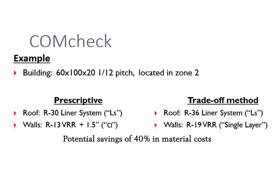
Using COMcheck not only proves compliance, it can also potentially save time and materials with alternatives to the prescriptive path. For example, consider a 60 by 100 by 20-foot metal building located in Climate Zone 2. The prescriptive path requires the following roof and wall insulation:
Roof: R-19 + R-11 Liner System
Walls: R-13 + R-6.5 (CI)
Using the performance-based method by increasing the roof system to an R-36 liner system and simplifying the wall system to a single layer of R-19 fiberglass insulation would result in a material cost savings of 40 percent (at current average insulation prices) with no sacrifice in performance. This example illustrates the concept of value engineering which seeks the best performing solution at the lowest cost. In this way, COMcheck can be used both as a compliance and optimization tool.
CI and Thermal Spacers
Heat and Thermal Conductivity
In order to understand energy code requirements on new construction, it is helpful to look at some of the basics of heat and thermal conductivity related to energy code compliance:
- Heat: energy stored in the movement of molecules.
- Conduction/Thermal Conductivity: flow of heat through solid bodies in physical contact, driven by collision of molecules, described by thermal conductivity, a fundamental property of solids.
- Convection: flow of heat resulting from currents in a fluid state by changes in density due to a temperature difference; also driven by molecule collisions, but is not contained within a crystalline structure.
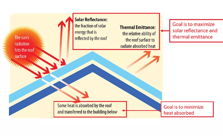
- Radiation: emitted electromagnetic radiation; driven by emissions of photons; only method of heat transfer that can permeate a vacuum. Radiation is of primary concern and requires that other concepts be defined:
- Reflectance: the amount of energy reflected by a body relative to the energy incumbent upon it; reflectivity is presented as a value between zero and one: zero means all energy is absorbed or transmitted; one means all is reflected.
- Blackbody: a theoretical object that absorbs all radiation energy incumbent upon it, turning it into heat at the same temperature (emissivity): - live.
- Emittance: the amount of energy radiated by a body relative to that emitted by a blackbody (how effective an object is at cooling itself off by emitting radiation); higher emissivity = higher rate of “cooling off.”
- Reflectance + Emittance = Solar Reflectance Index (scale between 0 and 100; higher numbers represent higher reflectance; standard black SRI = 1; standard white SRI = 100).
- Windows are evaluated through the following properties:
- SHGC (Solar Heat Gain Coefficient): the ratio of solar energy absorbed and transmitted to the incident amount.
- VLT (Visual Light Transmittance): the ratio of light transmitted through a window to the incident amount.
- U-Value: the thermal conductance of a component or assembly, as expressed in BTU/ (hr.ft2.F).
- Shading Coefficient (older, not as common): the SHGC of a window compared to the SHGC of a clear 1/8-inch pane of glass.
One of the more challenging requirements found in the prescriptive tables of ASHRAE 90.1 and the IECC is the use of CI. The use of rigid board insulation as CI in the field can be expensive and labor-intensive to install—though it may be a good choice for retrofits. The placement of CI in wall assemblies can require longer panel attachment screws, modified trims at base and framed opening conditions, and possibly longer roof panels to extend past the entire wall assembly. The use of U-factor compliance allows for alternative assemblies that do not include CI. Insulated Metal Panels (IMP) can also be a viable solution to satisfy a CI requirement while minimizing the number of components in a wall assembly.
The prescriptive tables may also require R-5 thermal spacers in standing seam roof assemblies. This is because the tables are based off of computer modeling and hot box testing of assemblies that happened to have R-5 thermal spacers. However, the “U-factor method” (for both ASHRAE 90.1 and IECC) does not specify thermal spacer size or purlin space requirements; meaning that code compliance can be achieved without a thermal spacer at all.
Since U-factor compliance can be a more complicated approach, it tends to be avoided. It requires hotbox testing or computer modeling to determine the U-factor of the roof assembly, taking into account the actual R-value of the thermal spacer as well as purlin spacing and the clip stand-off dimension. Fortunately, Owens Corning in conjunction with ASHRAE published a paper in 2010 that offers a calculation method based on modeling and testing of a generic system that will take into account any R-value thermal spacer and purlin space. This information, when put into COMcheck or other energy code compliance check software, can be used to show compliance without the use of R-5 thermal spacers.
Looking Ahead: Envelope- Based Solutions
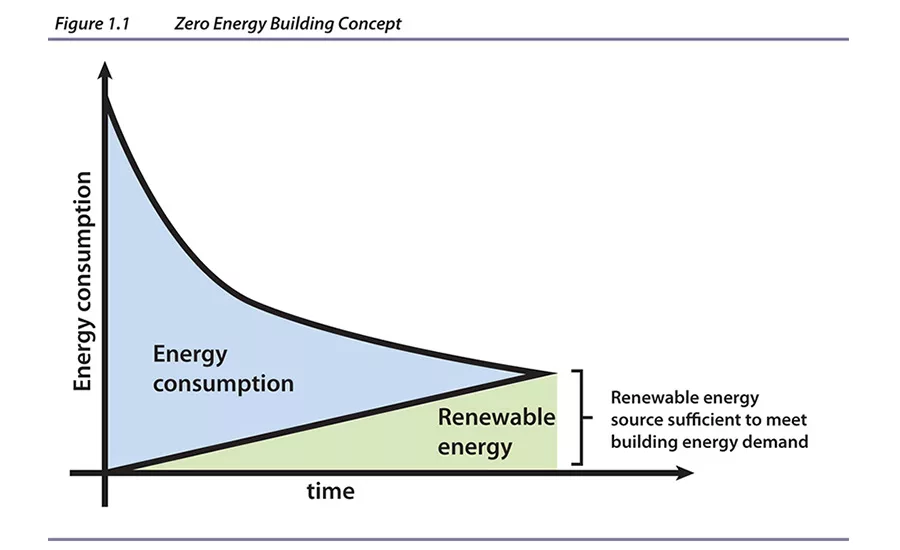
No matter which code a state or jurisdiction follows, future codes will become even more stringent. ASHRAE 90.1-2013/IECC 2015 represents a 15 percent improvement over previous versions. In addition to increased insulation values, the newer code includes improvements in air infiltration, increased HVAC efficiency and daylighting. These improvements represent one of many steps to the ultimate goal: net-zero energy buildings, combining reduced demand with renewable energy systems. By the time we see ASHRAE 90.1-2025/IECC 2027, that goal will no longer be a distant reality; it will be the norm. The best thing you can do now is to anticipate these changes and prepare for them.
Several trends, including more demanding energy codes, green building rating systems such as LEED, and legislative requirements such as California’s net-zero energy building mandate, are driving increased performance of the building envelope. At the same time, many customers have a lack of experience with the new requirements and a dearth of technical resources. The competitive nature of the construction industry makes it hard for builders to take the time to get up to speed. For projects without a single A/E and CM firm overseeing both design and construction, the increased performance requirements make projects more expensive and difficult to design. They also create a “proof of compliance” vacuum that can result in increased difficulty getting permits and certificates of occupancy across the nation.
Customers need help resolving these issues, and manufacturers can be supportive partners. Many provide envelope-based solutions that help meet stringent newer code requirements. In addition, some provide custom solutions based on COMcheck and provide support throughout the process. We are seeing increased collaboration between manufacturers (those who provide metal building components and insulation manufacturers, for example), enabling them to provide holistic solutions that meet several project goals at once.
Meeting Energy Code Requirements
Many building manufacturers offer insulation systems as part of their building package to minimize conflicts with the building design. Let’s take a look at some of these options.
Insulation is a cost-effective solution, easy to obtain and install. Systems are specifically designed for use with metal buildings, which allow for absorption of a small amount of condensation. These solutions also provide a clean and finished look to the building interior. Here are some typical higher performance insulation solutions for metal building roofs and walls:
Filled Cavity or “Long Tab” Systems: consisting of two layers of insulation, the bottom faced layer runs parallel to the purlins within the cavity and is supported by steel banding fastened to the bottom of the purlins. This layer has extra wide tabs (typically 12-15 inches) that wrap around and cover the tops of the purlins. The second layer is unfaced and runs parallel to the purlins, as well.
Liner Systems: these consist of two layers of insulation, both unfaced. The bottom unfaced layer runs parallel to the purlins, while the top unfaced layer runs perpendicular over the purlins. Steel banding is fastened to the bottom of the purlins to support a continuous fabric liner that acts as the vapor barrier. The steel banding and fabric together support the unfaced layer of insulation on the bottom. This system also can be used for wall applications.
Filled cavity and liner systems have the potential for improved thermal performance since compression of insulation is minimized. However, proper design and installation of these systems is critical to achieve rated performance.
“Sag and Bag” or Double Layer Systems: these involve a layer of faced fiberglass insulation draped across and sagging between the purlins. This layer is followed by a second layer of unfaced fiberglass insulation installed above and between the purlins.
Insulated Metal Panels
Designed for use in both wall and roof applications, IMPs are comprised of highly energy efficient, factory-controlled foam insulation sandwiched between a finished metal exterior and an interior face. At R-7+ per-inch, the insulating value of the closed cell polyisocyanurate core provides exceptional thermal performance, and the panels allow for fast, efficient construction. These products offer nearly three times the insulation efficiency as a field-assembled fiberglass system. An IMP that is around 3 inches can achieve R-20, whereas a wall system utilizing fiberglass with a separate liner would need to be approximately 7.5 inches thick.
IMPs are generally more expensive compared to fiberglass, but they can save labor costs with a single installation. This solution also leaves purlin and girt cavities free for other trades (e.g. electrical and plumbing). IMPs work well with standard metal building girt and purlin spacing. There are also solutions available for cold storage and applications requiring fire-rated assemblies.
Both IMPs and fiberglass insulation are ideal solutions to meet code depending on project requirements and specifications. Both products typically can be installed by the crews who erect the building. Manufacturers test their assemblies to ASTM C1363 and are able to provide tables with calculated U-factors for some typical wall and roof assemblies using their products and systems.
Coordination of Envelope Systems and Building Design
An increasing percentage of roof assemblies now require insulation to be placed inside the purlin cavity as well as over the purlin. As a result, building manufacturers have to adjust their bracing systems to avoid interfering with the insulation system.
The Air Barrier Requirement
The purpose of an air barrier is to limit uncontrolled air leakage into and out of the building’s envelope. Air leakage, sometimes called infiltration, can be caused by wind, stack effect and mechanical equipment, and uncontrolled leakage can result in increased energy usage, as heat or cooling is lost.
Air barriers are part of both ASHRAE 90.1 and the IECC. ASHRAE 90.1-2010 includes an air barrier requirement for non-residential spaces, while IECC 2012 includes an air barrier requirement for conditioned spaces and provides specific details on identifying, joining and sealing air barriers.
There are three air barrier code compliance options within ASHRAE 90.1 and IECC: Materials Compliance Option; the Assembly Compliance Option; and the Whole Building Compliance Option. Materials and Assembly Options are simpler, in that they only require testing of the air barrier material or assembly that includes an air barrier and the manner in which it is joined to other components.
The third option uses blower door testing to test air leakage of the building as a whole. It’s important to understand that, once this compliance path is taken, a designer cannot switch to the Materials or Assembly testing later. If the building fails the blower door test, the contractor must take corrective actions until it passes.
The air barrier can be located on the interior of the envelope (vapor barrier), the exterior of the envelope (metal siding), or somewhere in the assembly. In metal buildings, the vapor barrier is often used as the air barrier, and all vapor barriers have been tested to ensure they will meet the materials option. IECC and ASHRAE 90.1 both include lists list of materials that can be used as the air barrier; however, any material tested with an air permeance < 0.004 cfm/ft2 under a pressure differential of 0.3 in w.g. can be used. Proper joining of the materials is necessary for the material to perform adequately.
The interior option exposes the air barrier to potential damage from other trades or building occupants. The exterior option exposes the air barrier to damage from movement, as any air-sealed exterior product is at risk of failing over time as the building moves. Locating the air barrier within the assembly offers the most protection from failure.
With a liner or filled cavity roof system, it is good practice to ensure the entire cavity is filled with insulation. For example, a common R-30 liner system consists of 6 inches of unfaced insulation in the purlin cavity and 3.5 inches over the purlins. With 8-inch-deep purlins and a standing seam roof, this will properly fill the cavity. However, if the building has 10-inch purlins, it will create an air gap where condensation can form. Increasing the amount of insulation in the cavity can help prevent this.
Manufacturers often offer windows, insulated doors and other accessories specifically designed for use in metal buildings. As the approach to energy performance becomes more holistic and comprehensive—and especially as the goal becomes net-zero energy—all elements will have to be considered in relation to each other. For instance, adding windows and/or skylights will come with an energy penalty, but they will enhance daylighting and potentially reduce the reliance on artificial lighting. Similarly, a roof will no longer be considered just for its impact on the building envelope but for its capacity to facilitate renewable energy. The size of a renewable energy system, in turn, will depend on overall energy demand and size of the HVAC system. Coordinating all of these elements will require more communication between the architect/engineer and builders, among manufacturers, and between manufacturers and clients.
Manufacturers who supply multiple envelope components and especially those who can leverage tools such as COMcheck to optimize assemblies will have the advantage.
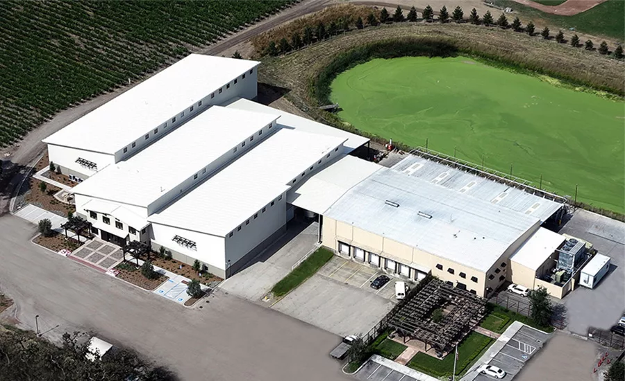
Case Study: Balletto Vineyards and Winery
Balletto Vineyards and Winery is a highly complex, seven-building project located on the southernmost tip of the Russian River Valley in Santa Rosa, Calif. The winery is a mixed-use facility that includes office space, a tasting room, a crush pad area, a fermentation room and spacious barrel storage. This project consists of a custom-engineered metal building system and IMPs.
The Challenge
From the very beginning, the owner established energy efficiency as one of the project’s main objectives. This directive had to be factored into a complex design that called for functional space to accommodate the different stages of winemaking and a multifaceted layout designed to create workflow efficiencies. Additionally, the project had to meet California’s Title 24 building regulations and standards. Title 24 has rigid energy codes designed for maximum efficiency; in many cases, projects are often required to meet local building standards, too. With such an extraordinary number of special needs and requirements, the project’s degree of complexity easily reached level 10, based on the Metal Building Manufacturers Association (MBMA) standards.
The Solution
To help successfully complete the project, the builder brought in the panel manufacturer who proposed an envelope-based solution that was aesthetically pleasing yet functional; most importantly, it incorporated the owner’s energy efficiency goals, which were critical to Title 24 compliance:
- Roof and wall insulation was optimized using IMPs. At the base of the building, the wall panels consist of 6-inch-thick panels, which are installed horizontally to create a wainscot up to 7 feet and 2 inches. From there to the roofline, 4-inch CF panels are installed vertically. The panels are Antique Bronze and the CF panels are Sandstone, matching the roof. Sandstone has a high solar reflective index (SRI), which contributed to the building’s LEED points.
- Superior thermal performance of the IMPs enabled the application of a night air cooling system in lieu of installing air conditioning units; this approach reduces not only energy consumption but also daily operating costs.
- Use of individual high-side wall clearstory windows maximizes daylighting inside the building without penetrating the roof.
- The single sloped roof planes and partial gable roof planes are south facing to accommodate optimum solar panel exposure.
- Incorporating the fermentation room and wine barrel storage into the winery design eliminated the need to rent an offsite warehouse for storage and also reduces fuel costs, since these work areas are within walking distance.
The effectiveness of the project design and the application of energy-efficient products significantly reduced the operation’s carbon footprint, and consequently, simplified the process of attaining Title 24 compliance.
References
- Energycodes.gov, BECU_Codes_101
- ©2016 ACEEE Summer Study on Energy Efficiency in Buildings
- Energycodes.gov, BECU_Codes_101
- energycodes.gov, U.S. Department of Energy: 2015 IECC Commercial Scope and Envelope Requirements; https://www.energycodes.gov/sites/default/files/becu/2015_IECC_commercial_requirements_ envelope.pdf)
- Energycodes.gov,BECU_Codes_101
- Energycodes.gov,BECU_Codes_101
- Energycodes.gov,BECU_Codes_101
- ENERGY CODES AND STANDARDS by Martha G. VanGeem CTLGroup; Revised and updated by Ryan M. Colker; Sustainable Buildings Industry Council; Updated: 10-24-2016, from the Whole Building Design Guide, a program of the National Institute of Building Sciences.
- ENERGY CODES AND STANDARDS, by Martha G. VanGeem BE
To complete the quiz and receive a certificate of completion, follow this link: http://bit.ly/BESUMMER2017D
Looking for a reprint of this article?
From high-res PDFs to custom plaques, order your copy today!
.webp?height=740&t=1767036885&width=auto "Header - BE 1170x658 (002).png")

.webp?height=740&t=1755781744&width=auto "KEE(2).png")