CEU: Emerging Building Envelope Solutions

The Irsay Family YMCA at CityWay in Indianapolis, Ind. Photo courtesy of Douglas Adams and Browning Day Mullins Dierdorf.
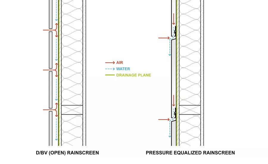
Diagrams of a Drained/Back Vented (Open) Rainscreen and a Pressure Equalized Rainscreen (PER). Illustration courtesy of author.
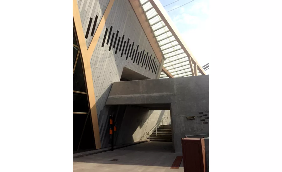
Simon Skjodt International Orangutan Center (IOC) at the Indianapolis Zoo. The primary wall assembly of the exhibit structure is protected by a D/BV (open) rainscreen comprised of GFRC panels. Photos courtesy of author and Browning Day Mullins Dierdorf.

Simon Skjodt International Orangutan Center (IOC) at the Indianapolis Zoo. The primary wall assembly of the exhibit structure is protected by a D/BV (open) rainscreen comprised of GFRC panels. Photos courtesy of author and Browning Day Mullins Dierdorf.

Among other envelope systems employed at the Irsay Family YMCA at CityWay in Indianapolis, Ind., the facility utilizes a PERs system in the form of a metal panel cladding along the fascia and soffit of the signature roof feature. Photo courtesy of Douglas Adams and Browning Day Mullins Dierdorf.

Aesthetics and energy efficiency prompted the use of silkscreened images on insulated glass units at the Minneapolis Central Library. Photos courtesy of author.

Aesthetics and energy efficiency prompted the use of silkscreened images on insulated glass units at the Minneapolis Central Library. Photos courtesy of author.

Exterior sunshades installed at the Indianapolis Museum of Art. Photo by Keith Clark and Browning Day Mullins Dierdorf.

The Indianapolis Museum of Art. Photo courtesy of Greg Murphy and Browning Day Mullins Dierdorf.

An undulating extensive green roof atop the California Academy of Sciences in San Francisco, Calif. Photo courtesy of author.

Pulliam Square in Indianapolis, Ind., features an outdoor living wall system. Photo courtesy of Barth Hendrickson and Browning Day Mullins Dierdorf.


Stages of Design and Types of Energy Models
Figure adapted from An Architect’s Guide to Integrated Energy Modeling in the Design Process, p. 8. Original image courtesy of the American Institute of Architects.
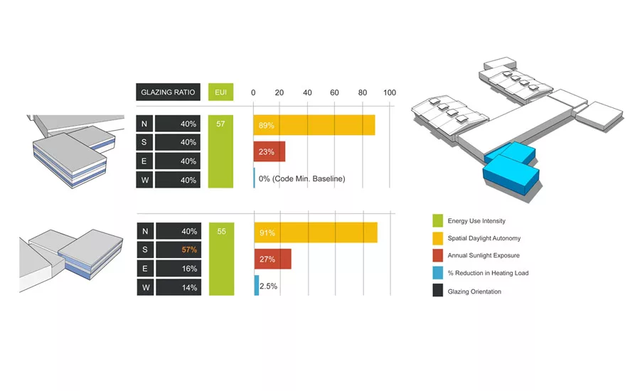
Design performance modeling can help design teams go beyond oversimplified rules-of-thumb toward better informed decision-making based on predicted performance outcomes. Figure courtesy of author and Browning Day Mullins Dierdorf.
NIBS Guideline 3 for BECx is available for free through the online WBDG. Image courtesy of NIBS.
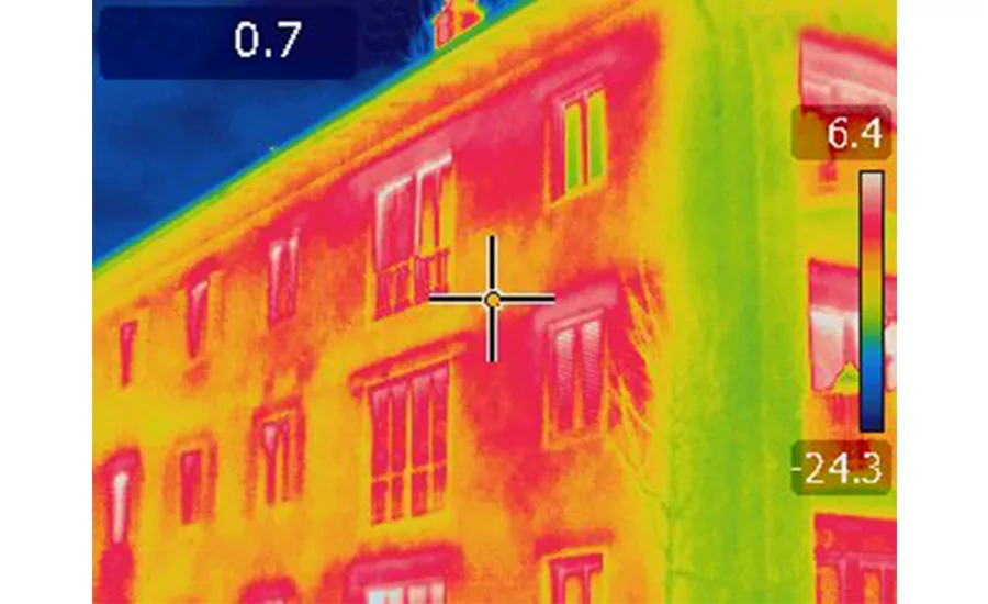
BECx can help project teams identify issues in the field related to a range of damage functions and rectify them before the project is complete. Pictured here is an infrared thermal imaging scan of an exterior envelope condition.
Innovative trends in building envelope design, construction and commissioning are helping teams deliver high-performance enclosures to meet challenging project requirements.
Climatic factors have a direct effect on the built and natural environments. As professionals in the design and construction industry, we make decisions on our projects that will influence this effect. Building envelopes offer a unique opportunity for our built environment to tap into the natural energy flows of a site, utilize local material palettes, take advantage of the lessons offered by a region’s indigenous building archetypes, or take a cue from natural systems with an approach grounded in biomimicry.
LEARNING OBJECTIVES
After reading this article, you should be able to:
- Recognize the significance of building enclosures and identify the basic damage functions of any building envelope assembly.
- Identify multiple types of emerging building envelope products and technologies and explain their potential durability and sustainability advantages.
- Assess the performance aspects of building envelopes and explain the role and potential benefits of design performance modeling.
- Explain the basics of building enclosure commissioning (BECx) and potential benefits of implementing such services on a project.
Defining Building Envelope
The “building envelope” can be defined as that portion of the building that separates the interior and exterior environments in terms of energy (light and heat), water (in all its forms), air, pests and even people. As we consider the building envelope as a distinct part of a building, we recognize that its success and performance is in large part determined by the integration of its assemblies and components as well as the building envelope’s integration with the other building systems. The building envelope typically has at least six sides—four walls, the floor and the roof—and its performance relies on the characteristics of every side and especially their intersections.
Toward High-Performance
This article will focus on emerging trends in high-performance building envelopes that are viable in the market today. The term “high-performance” may seem a bit abstract—and it can mean different things to different contributors and stakeholders on a project. For the purposes of this article, high-performance is considered to exhibit four major aspects: safety, comfort, thriftiness and durability. Much of the building envelope’s contribution to a building’s overall performance is significant and direct, but this is not always the case.
To complete the quiz and receive a certificate of completion, follow this link: bit.ly/BEWINTER18
A high-performance building envelope may make direct contributions to safety in terms of indoor air quality, but much of this contribution is actually indirect. For example, proper moisture management accomplished by the building envelope fosters improved indoor air quality by mitigating mold and mildew growth, but its contribution to this condition is indirect and certainly not determinant because plenty of other building elements and systems will contribute to indoor air quality as well.
Certainly, as the separator between environments, the building envelope is a major contributor to thermal, visual and acoustic comfort. As the separator from the exterior environment, the building enclosure manages the transfer of heat, light and sound.
The characteristics of an envelope assembly will impact energy performance and maintenance operating costs. The longer and the more distinct the environmental separation we ask the building to accomplish, the greater the stress we place on the envelope elements that serve to establish the environmental separation. However, a well-designed and constructed building envelope assembly can better withstand formidable climatic conditions and endure for decades.
The Major ‘Damage Functions’
We demand many functions from the building envelope. We prioritize the major damage functions of the building envelope in the following order:
- Liquid water (bulk and capillary)
- Airborne water
- Vapor
- Solar radiation
- Heat fluctuations
- Pests
- People
The first three damage functions are related to moisture management. Even in arid climates, water in all of its forms represents the number one challenge to building envelope performance, service life and durability.
Solar radiation—and subsequent heat fluctuations—can be an important damage function for certain types of exterior finishes, especially at higher altitudes and/or where incident solar radiation is high. Typically, solar radiation is a second or third order damage function in comparison to any of the other forms of moisture.
Pests, especially insects, can be a dominant damage function for building envelopes; however, pests almost always need a partner—moisture—to be a first-order threat. Water intrusion oftentimes results in deterioration and fertile ground for pests.
People, full-time occupants and transient visitors alike, and what they do (and do not do—e.g., maintenance) to both the building envelope and the mechanical systems of a facility can post major challenges to building envelope performance. Our building envelope assemblies are constantly subject to many forces which can inflict damage. If neglected, these points of vulnerability can become expensive failures.
A complete and adequate building envelope solution must withstand all of these phenomena.
Emerging Building Envelope Solutions You Can Use Today
The proceeding sections of this article offer a primer with regard to emerging, yet market-ready, solutions in building enclosures with an emphasis on wall systems. The building design and construction industry is changing at a rapid pace. Amidst the many developments, three key trends can be identified:
- Innovations in technologies and products
- Design performance modeling
- Building enclosure commissioning
Innovations in Technologies and Products
There are many emerging innovative envelope solutions in the marketplace today. For the purposes of this article, we will consider four categories of envelope assemblies: rainscreens, glazing assemblies, green roofs/walls, and all-in-one wall assembly solutions.
As mentioned earlier, the building envelope must face a number of damage functions—and bulk water is public enemy number one.
In general, there are four basic approaches to bulk water management in a wall assembly:
- Barrier: Barrier surfaces are designed to shed water without allowing any moisture penetration. Barrier-type exterior insulation finish systems (EIFS) exemplify the barrier system.
- Mass: Traditional uses of concrete, masonry, timber structures and other solid assemblies that are capable of serving as hygric buffers will shed most bulk water, absorb the remainder, and slowly release the absorbed moisture as a vapor.
- Internal drainage plane: The plane located between the exterior cladding and supporting wall that serves as a redundant moisture barrier. Stucco or clapboard walls will often contain a dedicated internalized drainage plane.
- Rainscreen: Rainscreens manage moisture through cladding, an air cavity, a drainage plane and an airtight supporting wall system. These systems diminish the various forces of moisture-drive into a wall assembly.
Although they are becoming increasing popular in recent years, rainscreens seem to be the most broadly misunderstood assembly type.
Rainscreens
The term rainscreen has been generalized in the building design and construction industry. In essence, there are two basic types of rainscreens:
- Drained/Back Ventilated (D/BV)
- Pressure Equalized Rainscreens (PERs)
Drained/Back Ventilated (D/BV)
In this broad category of rainscreens, a continuous air space is provided. In some fashion, an air space between the cladding and exterior wall must be open enough to facilitate drainage and drying.
Ventilated rainscreens are open at the top and bottom of the air space to allow airflow and convective drying when water works its way behind the cladding through wind-driven rain, bulk water shedding, capillary action through the cladding, and so on. This interstitial cavity should be protected from bulk water and pests with overhangs and screens.
Vented rainscreens are open at the bottom of the air space. These systems encourage drainage but do not have sufficient airflow to enable convective drying.
Open rainscreens feature cladding with completely open vertical and horizontal joints. The drainage plane in this variety of D/BV rainscreen will be exposed to ultraviolet radiation, which could degrade the system over time.
In general, D/BV rainscreens are most appropriate for climates with less than 60 inches of annual precipitation. The marketplace for cladding material has expanded greatly in recent years. Traditional solutions such as terracotta, fiber cement panels and wood still exist, cutting-edge solutions are emerging that utilize glass fiber reinforced concrete (GFRC), ultra-high performance concrete (UHPC), phenolic panels and large-format quartz. These newer cladding solutions are durable with excellent dimensional stability, resistance to freeze/thaw degradation and notable color stability.
Pressure Equalized Rainscreens (PERs)
This category of rainscreen is effective in all climates and provides a great option for locales that receive more than 60 inches of rain per year. PERs represent an advanced version of simple D/BV rainscreens. They integrate porous exterior cladding with compartmentalized air spaces, generous ventilation and a support wall that is tight to both air and water.
PERs get their name because they terminate wind-induced pressure differentials across the cladding system. The compartmentalized air cavity promotes rapid air pressure equalization—thus, minimizing moisture intrusion. When wind-driven air enters openings in the bottom of the cladding system, the air mass in the compartment “pushes back” as it has nowhere to escape. This prevents wind-driven rain from entering the wall system. If a small amount of rain is driven into the cavity, the same openings allow the water to drain via gravity. PERs are typically employed in several commercial cladding systems, such as metal panel systems.
All types of rainscreen systems require carefully coordinated design and detailing. As a result, they may be more expensive than other cladding options. However, especially in wet climates, they may encourage greater resistance to moisture-related forces by keeping moisture off of the wall assembly. Composite metal panel products can provide lightweight, rigid PERs solutions with complex textures and geometries. While traditionally utilizing an aluminum facing, recent composite metal panel offerings feature zinc, copper, stainless steel and titanium.
Insulated metal panel systems offer another innovative twist on PERs. With an insulation value as high as R-21 for a 3-inch-thick panel, insulated metal panel solutions feature pressure-equalized joinery to provide long-term protection with minimal maintenance, whereas a barrier-seal system depends on the accurate and consistent placement of the sealant and may also require periodic maintenance. Additionally, a vented horizontal joint is usually part of an insulated metal panel system and is designed for pressure equalization.
Even in the presence of an imperfect air barrier, the joinery maintains the system’s performance integrity. By comparison, imperfections in a barrier seal system can lead to water infiltration and subsequent damage. As some insulated metal panel systems are emerging that utilize specialized joinery in lieu of backup sheathing, the potential exists for this one product to provide a complete wall system solution by constituting the air, water and thermal barriers as well as the vapor retarder.
Glazing Systems
Improved energy efficiency continues to be one of the strongest trends in building envelopes. This is driven by increasing stringencies in our energy codes and rating systems. However, glazing assemblies are typically the weak spot in the envelope’s thermal barrier. In response, glazing manufacturers have responded by developing several new types of glazing products.
Glass Treatments
Beyond standard double-glazed insulated glass units, manufacturers are offering triple-glazed solutions (sometimes accomplished with intermediate films rather than glass), filmed interlayers, low-emissivity coatings, gas infills, ceramic silkscreens, acid etching, electrochromic interlayers to change the tint of the glass, and low-iron additives and other alterations for increased clarify and full-spectrum light transmittance.
There is more variety than ever before when it comes to glass types. The various treatments achieve a variety of aesthetic and performance outcomes as the industry trends toward fine-tuned glazed façades by customizing glass types to varying orientation and exposure in order to achieve better energy performance and greater visual and thermal comfort.
Framing Systems
But glazing advancements only address part of the problem with it comes to energy. The framing system that supports the glazing often undermines the improved thermal performance of the glazing itself. Conductive heat transfer through thermal bridging at the frames will most often decrease the overall assembly U-factor of the glazing system. Fortunately, there have been a number of advances here as well.
In addition to simplified construction techniques and options for factory-fabrication to shorten lead times, advancements in curtainwall and storefront framing systems permit continuous thermal breaks to meet increasing energy performance requirements.
Solar Control Devices
When it comes to solar control, the de facto solutions tend to be interior devices such as drapes and blinds. While such solutions may help mitigate intense sunlight, they also tend to cut views. Moreover, interior solar control devices do little to reduce solar heat gain through the glazing assembly. The best approach to reduce heat gains from direct solar radiation is to keep the sun’s rays from directly striking the glazing assembly.
Enter exterior solar control devices such as overhangs, screens and sunshades. These devices may be fixed or automated and come in a variety of shapes, profiles and fastening options. They offer a bold aesthetic solution that can add up to superior energy savings. Research has shown that external shading devices can reduce solar heat gain through glazing by up to 80 percent.
Sunshades in particular have been popular in Europe for several years, but are now becoming more common in North American projects. Sunshades can be cantilevered or suspended. They can be customizable, allowing designers to select from a wide variety of blades, outriggers and fascias. Projections can typically be up to 5 feet in depth in order to suit a project’s shading requirements.
High-Performance Translucent Buildings Systems
On the topic of glazing assemblies, the next generation of high-performance translucent building systems offer a budget-friendly, elegant side-lighting solution. From single-story to mid-rise construction, these wall systems convert sunlight into glare-free ambient daylight with minimal heat exchange. Typically factory unitized, these systems are among the most highly insulated light transmitting fenestration solutions on the market.
The glazing units are filled with aerogel, a synthetic porous ultralight material derived from silica, and a liquid solvent such as ethanol. The aerogel is what gives the translucent panels their superior thermal performance versus typical insulated glass. In addition, translucent building systems are available with options for high-impact, hurricane rated walls and windows, a Class A fire rating and blast resistant construction. Modern advancements have also thwarted the infamous “yellowing” that tended to occur in past generations of the products as a result of prolonged exposure to ultraviolet solar radiation.
Structural Glass
An emerging marketplace for structural glass wall solutions is enabling designers to enhance structures with impressive, expansive areas of total vision. They function as a type of curtainwall system consisting of glass that is bonded or anchored back to a structure without continuously gasketed aluminum pressure plates/caps. The glazing units can be comprised of virtually any type of glass—including insulated glass units. The backup framing system may be aluminum mullions similar to a traditional curtainwall system. However, contemporary product offerings may consist of glass mullions, steel blades, stainless steel spider fittings, cables or stainless steel rods. The system may use extruded silicone/ethylene propylene diene monomer (EPDM) gaskets or a wet-sealed silicone.
There are many aesthetic virtues of a structural glass system including a nearly seamless, continuous glass look with less visual interruptions across a façade. They can resist wind and snow loads. Some systems can resist seismic forces. There are notable relative energy performance attributes as well. Traditional curtainwall systems can conduct large amount of heat transfer through the metal framing. With little to no exposed exterior metal, structural glass exhibits less thermal bridging.
Green Roofs and Walls
In response to an increasing desire to add green spaces and visual connections to nature within the built environment, verdant surfaces—i.e., green roofs and walls—have been growing in popularity. Today, the marketplace provides a diverse array of options to suit a wide range of project types. Incorporating vegetation into building envelope solutions offers a unique dimension of texture, symbolism and seasonal dynamism to a structure.
Green Roofs
In the most simplistic of terms, green roofs can be defined as planting beds installed atop a building’s roof structure. Amidst a spectrum of variations, green roof systems are typically defined by three classifications: extensive, intensive and semi-intensive.
Extensive green roofs are the shallowest of the three classifications. With an overall depth between 3–5 inches, the fully saturated weight of this system will typically vary between 15–25 pounds/square-foot. Extensive green roofs will typically exhibit hardy species of mosses, sedums, succulents, herbs and some types of grasses. This classification of green roof may not require permanent irrigation and is relatively low-cost and lowmaintenance. However, the potential for rainwater sequestration is minimal and it is not capable of harboring a diverse array of plant species.
Intensive green roofs are on the other end of the spectrum. This classification of green roof will range from 7-over 24 inches in depth, correlating with a saturated weight of 35-over 80 pounds/square-foot. Dependent on the system depth and irrigation, intensive green roofs can support the widest range of plants including perennials, turf grass, putting green, vegetable gardens, shrubs and many species of trees. Intensive green roofs require permanent irrigation systems and can contribute meaningfully to rainwater sequestration.
Semi-intensive green roofs constitute the middle ground between the extensive and intensive classifications. Typical depths range from 5–7 inches. The saturated weight will usually vary between 25-over 40 pounds/square-foot. Some irrigation may be necessary as semi-intensive green roofs are capable of supporting perennials and shrubs in addition to the succulents and other small plants supported by less intensive green roofs systems.
Green roofs may be built-up atop a building’s roof structure or modular tray systems can be installed atop a slip sheet over a low-sloped membrane roof system.
In response to unique requirements on a number of green roof installations, the industry has introduced several innovative systems components to the market. Some installs offer unique clip systems that fasten to draped stainless steel mesh to hold growing media along a sloped roof. In order to address concerns about leak detection, a manufacturer has developed a low-voltage test method that creates an electrical potential difference between a non-conductive membrane surface and the conductive structural deck or substrate, which is earthed or grounded as part of the green roof system. The result is a non-destructive method of waterproofing verification and pin-point leak detection.
Green Walls
Exterior green wall systems can be defined by two basic classifications: living screens and living walls.
Living screens refer to the broad category of green wall systems that consist of climbing vines and ivy on walls, cables, scaffolding, modular mesh systems and so on. While the concept of plants growing up a façade is not new, research has shown that over time many species of plants can damage wall cladding, which presents long-term durability concerns. In response, some manufacturers now offer products specifically designed to foster plant growth while keeping the vegetation off of the wall itself.
Living walls are defined by the dense, vertical gardens that are harbored by a modular systems affixed to the building structure. Some living wall systems may grow plants hydroponically within a water-soaked mesh fabric, while other systems may employ lightweight soils (similar to the growing media used for green roofs) in fabric pockets or trays.
Most green wall systems require permanent irrigation and project teams should coordinate with installers to ensure that methods are identified to ensure the delivery of nutrients and fertilizers as necessary. Living walls are more robust than living screens and thus have the potential to provide a far more diverse pallet of flora. However, living walls also require more maintenance.
All-in-One Systems
Design and construction teams have witnessed the rise of an increasingly complicated field of construction specifications. For any given project, there is a high likelihood that the contract documents contain technically incompatible specifications. Most of the time these issues can be identified and worked through in the field. However, if undetected, they can make components of a building envelope assembly susceptible to failure, leading to damages, voided warranties and claims.
In order to take away the guesswork and foster consistent, compatible project specifications, multiple industry leaders in different trades have aligned in order to offer complete (i.e., all-in-one) wall systems. In essence, the notion is to have one assembly solution from a single supplier with a single-source warranty.
These all-in-one assemblies have been engineered to bring together sophisticated, category-leading components that are completely compatible, code compliant and warrantied to work together to deliver outstanding performance—and bring high-performance building envelope solutions to the next level for architects and contractors. They come with comprehensive details and quality assurance programs. Today, there are systems for wood studs, metal studs and concrete masonry unit (CMU) wall assemblies.
Design Performance Modeling
The building design and construction industry is becoming ever more attuned to high-performance outcomes. Design teams and clients alike are becoming more sophisticated with regard to building science and energy conservation measures. Consequently, there is a growing expectation that project teams leverage the tools and technical resources necessary to go beyond oversimplified rules-of-thumb toward optimized building solutions grounded in performance-driven outcomes as part of an integrative design process.
Increasingly, energy modeling—once the purview of engineers late in the design process—is being utilized as a decision-making tool from conceptual design through construction. This kind of early-stage energy modeling—often referred to as design performance modeling—is simplified through basic forms, generalizations and gross approximations, which makes it markedly different from the highly detailed comprehensive energy modeling effort typically executed near the end of the design process for green building certification and/or energy code compliance.
Software developers are meeting demand head-on. An emerging marketplace of easily accessible software tools is liberating early-stage design performance modeling opportunities for the entire design team. Many publicly funded research institutions provide specialized analysis tools for free, while various commercial developers offer more robust, comprehensive packages. Several design performance modeling tools are now available that integrate into project team workflows with building information modeling (BIM). Thanks to these platforms, any designer can compare the performance of various design options and refine strategies.
These early-stage tools are easy to use, the results are visually stimulating and online tutorials abound. However, the validity of the results—albeit preliminary in nature—necessarily hinge on the user’s knowledge in regards to building science. In application, much like construction costs estimating, projects teams must also acknowledge that energy models are only as accurate as their inputs and more refined information (and thus more accurate results) will be available later in the design process.
As part of an integrative process, design performance modeling provides teams with a dynamic opportunity to compare the relative performance of different building forms and envelope options at the earliest stages of design when most of the major decisions are made and the consequences of significant changes are minimal.
The Emergence of Building Enclosure Commissioning (BECx)
Over the past few decades, a growing importance of building envelope performance has been evidenced by the increased attention being paid to this topic by the building design and construction industry.
In 2004, the National Institute of Building Sciences (NIBS) Building Enclosure Technology and Environmental Council (BETEC) and the American Institute of Architects (AIA) signed an agreement to establish the Building Envelope Council (BEC) initiative.
The initial goal of the initiative was to have local AIA components establish at least nine BECs by May of 2007. Since then, the program has founded 26 BEC Chapters, representing both cities and states. Today, more than 3,000 affiliated architects, engineers, contractors, manufacturers and others with an interest in building enclosures participate in BECs around the country. The councils promote the exchange of information and facilitate discussion on topics pertaining to building enclosures and related science such as education, training, technology, climate conditions, local issues and more.
BECx in LEED
With LEED v4, BECx has a vehicle for more expansive market uptake. While not mandatory, under EA Credit Enhanced Commissioning project teams have the option to pursue two points for building enclosure commissioning. Under the option for “Envelope Commissioning,” LEED asks project teams to first fulfill the requirements in EA Prerequisite Fundamental Commissioning and Verification as they apply to the building’s thermal envelope in addition to mechanical and electrical systems and assemblies. Next, teams are asked to complete the commissioning process activities for the building’s thermal envelope in accordance with ASHRAE Guideline 0–2005 and NIBS Guideline 3–2012 as they relate to energy, water, indoor environmental quality and durability.
As a resource toward this effort, the NIBS, under guidance from the Federal Envelope Advisory Committee, developed a comprehensive guide for building envelope design and construction for office and institutional building types. The Building Envelope Design Guide (BEDG) is continuously improved and updated by the BECs and can be accessed (for free) through the online Whole Building Design Guide (WBDG), a program of the NIBS.
A development in the work of the BETEC is the creation of NIBS Guideline 3 for the Building Enclosure Commissioning Process BECx. NIBS Guideline 3 is intended to be used in concert with ASHRAE Guideline 0.
ASHRAE Guideline 0 and NIBS Guideline 3
ASHRAE Guideline 0: The Commissioning Process describes the quality-oriented “Commissioning Process” (CxP) capable of achieving, evaluating and documenting that a facility and its systems meet the Owner’s Project Requirements (OPR). The procedures, methods and requirements in Guideline 0 outline each phase of the project delivery and the associated commissioning processes from pre-design through occupancy and operation.
While ASHARE Guideline 0 outlines the commissioning process, NIBS Guideline 3 provides specific information related to commissioning the building enclosure. It is essential that a project’s commissioning authority (CxA) understand and comprehend the basic process provided in Guideline 0 as well as the specific BECx requirements of NIBS Guideline 3. The latter recognizes that, just like other critical elements of a building, an independent review of the commissioning process is an impartial way to see that the design and construction of façades, fenestrations, roofing and other envelope components are all carried out and tested appropriately to perform as intended. As stated in the document, Guideline 3 “provides recommendations for navigating the enclosure commissioning process from its necessary inclusion in project planning to its continued emphasis throughout the life of a building. The Guideline is intended to be usable by all owners for all building types.”
Regarding the process, NIBS Guideline 3 goes on to point out that, “The BECx process is utilized to validate that the design and performance of materials, components, assemblies and systems achieve the objectives and requirements of the owner. The BECx process achieves this through experience, expertise, modeling, observation, testing, documenting and verifying materials, components, assemblies and systems to validate that both their use and installation meet the owner’s requirements.”
BECx Process Primer
The notion of “building enclosure commissioning” may conjure up thoughts of on-site performance testing. While such exercises constitute an important aspect of BECx, the process involves much more breadth of scope. BECx should begin at pre-design and continue through post-occupancy—in the same manner as the more common mechanical and electrical systems commissioning process. In fact, BECx goes hand-in-hand with the more familiar scope of systems commissioning.
In accordance with NIBS Guideline 3, the process basically looks like this:
During pre-design, the BECx team typically contributes to initial budget estimates and provides third-party expertise regarding the most appropriate building envelope materials and assemblies, what types of testing may be needed, and how project performance targets (e.g., energy or water efficiency) and/or enclosure longevity can be best achieved within project constraints and budget limitations.
Over the course of the design development process, drawing reviews are critical for ensuring the continuity of various barriers that address the damage functions—particularly moisture management. Some drawing sets exhibit problematic details; a meticulous BECx drawing review can identify potential issues before they manifest themselves in the field.
During construction, mockups and on-site inspections take place with regularity. Testing mock-ups serve many needs of the BECx commissioning process throughout construction. The mockups can identify weak points in assembly design, help a team establish the most efficient construction sequencing, and serve in training exercises. Through on-site inspections, the commissioning authority can verify that sequencing is being executed properly and better ensure that field conditions will perform in accordance with the OPR.
Field testing occurs during the pre-occupancy phase and is just as vital as mockup testing. It is during this phase that the exercises most professionals associate with building enclosure commissioning take place. BECx protocol will ensure that an action plan is implemented to address insufficient field testing results. Ultimately, the building enclosure must meet the performance requirements specified by the owner.
During post-occupancy, BECx helps ensure that inspection and maintenance plans are in place for the building envelope and that critical documentation, such as warranties, are included in the owner’s manual and delivered to the owner.
Any building project can benefit from BECx. When a facility is not subjected to an appropriate commissioning process, it is highly likely that the owner will not end up with a building solution that performs as intended by the project team.
Conclusion
Building envelopes are becoming more sophisticated—much like the rest of the building design and construction industry. With this sophistication comes greater complexity and more robust procedures for design, construction and commissioning.
Emerging trends with regard to building envelopes will continue to evolve at rapid pace. The impetus is on design and construction professionals to stay abreast of emerging trends in the industry to help project owners successfully achieve their high-performance goals.
Case Study
Stages of Design and Types of Energy Models
The American Institute of Architects (AIA) has published a primer for design professionals interested in integrating energy modeling into the design process. The (free) publication, titled An Architect’s Guide to Integrating Energy Modeling in the Design Process, is a comprehensive 86-page document that defines the fundamentals of energy modeling, outlines the current state of various performance and analysis tools, and foretells the direction of an architectural industry increasingly focused on performance-based design processes.
Among other components of the document, the guide offers:
- A succinct introduction to many key terms related to energy modeling.
- Clarifications related to common misunderstandings about energy modeling.
- An outline of the cycle of benefits energy modeling enables throughout the design process.
- Several potential new and ongoing service opportunities for professionals well versed with energy modeling.
- A summary of the most palatable energy modeling tools in the market today.
In the simplest of definitions, the guide defines an energy model as “a calculation engine that accepts inputs such as building geometry, system characteristics, and operations schedules and produces outputs such as performance comparisons and compliance reports.” However, the guide acknowledges that the language surrounding energy and resource modeling can be confusing and that “energy modeling” can mean different things to project teams at different points in the design process. As such, it differentiates the four most common types of energy/performance modeling as follows:
Design Performance Modeling (DPM)
During the conceptual and schematic design phases, DPM informs decision-making by predicting project performance with respect to energy efficiency, daylighting, thermal comfort, natural ventilation and other factors. Typically deployed before engineering systems are fully specified, this level of analysis is less complicated and time-consuming than the more robust building energy modeling (BEM). DPM fosters rapid, iterative exploration of various design solutions and allows cost, aesthetics, and performance to be given value and considered among the project team and with the client—in real-time in some instances.
Building Energy Modeling (BEM)
BEM entails a robust, comprehensive modeling exercise that simulates a project’s anticipated energy use (and corresponding energy savings) as compared to a baseline condition. As such, BEM also demonstrates project compliance with codes and/or third-party certification programs. BEM is a level of modeling that most professionals think of when using the term “energy modeling” and it typically begins during the design development phase and is finalized concurrent with contract documents. BEM models are highly detailed, incorporating specific design values, mechanical equipment specifications, and assumptions about building operation and maintenance. BEM predicts annual energy performance based on Typical Meteorological Year (TMY) data.
Building Operation Modeling (BOM)
During the construction and operation phases of a project’s development, the BEM model can be calibrated based on data gathered from actual utility bills, occupant use patterns, hour of operations, functioning of systems, and actual on-site weather conditions. BOM is the embodiment of this “fine-tuning” of the energy model. The process of comparison of the BEM and the BOM is known as “calibrated simulation” and is the essence of Measurement & Verification (M&M) protocol. BOM has utility with regard to satisfying certain code requirements for post-occupancy monitoring. It can also be leveraged to analyze the value proposition of potential improvements on a project.
Project Resource Modeling (PRM)
PRM entails an extensive modeling exercise to assess multiple resource issues related to the development of a project. PRM constitutes a broad effort that can begin during conceptual design and may continue through occupancy. It may address issues reaching far beyond a building’s site energy including water consumption, solid waste, transportation, manufacturing, social and agricultural elements, embodied energy and carbon emissions among many other factors. PRM can assess existing and imported resources and can help teams better understand the interrelationships among resources.
To complete the quiz and receive a certificate of completion, follow this link: bit.ly/BEWINTER18
Looking for a reprint of this article?
From high-res PDFs to custom plaques, order your copy today!

.webp?height=740&t=1767036885&width=auto "Header - BE 1170x658 (002).png")

.webp?height=740&t=1755781744&width=auto "KEE(2).png")
.webp?height=200&t=1736534920&width=200 "Polyglass(2).png")