Small details can have an enormous impact. Get them right, and the likelihood of success can increase exponentially. Get them wrong, and the results can be disastrous.
This is certainly true in low-slope roofing. The details—from drainage to penetrations and edge metal—are essential to ensuring a roof’s long-term durability and performance. They are, however, also the source of the vast majority of roofing-related issues.
Some of these issues are, of course, the result of poor workmanship by the roofing contractor. Most, however, stem from improper roof design or specifying the wrong products for the job.
This article will outline seven points that, if kept in mind during the design process, can eliminate many roofing-related change orders and reduce installation time and costs.
Water MUST Leave the Roof
The following cannot be stated often or strongly enough: water MUST leave the roof AT ANY COST.
There are three ways to achieve the necessary slope to accomplish the goal: structural slope, tapered insulation, or a combination of tapered steel and tapered polyisocyanurate crickets.
Tapering structural steel is the least costly method and is generally used in new construction. Adding slope of 1/4-inch per foot to a 40-foot-by-40-foot span requires only a 10-inch difference in the grid line of the columns and lengthening the joists by 1/8-inch.
Using tapered insulation to accomplish the same task would require an additional 8,400 board feet of tapered insulation and, if mechanically fastening the insulation, fasteners in three different lengths. At today’s prices, this would add approximately $13,000 to the project’s cost.
The third option—a combination of structural steel and tapered insulation—is optimal. Primary drainage is accomplished by slope in the structure. Tapered polyiso crickets, with a slope of 1/2-inch per foot, supplement this by providing lateral movement to the drains and around projections.
Follow the 50 Percent Rule
The wider a cricket is, the faster water will flow to the drains or scuppers. Full diamonds should be used in the center of the roof and half diamonds used against walls. Following the “50 Percent Rule” ensures the cricket is properly sized to provide sufficient drainage. It directs that the half cricket—the distance from the center of the diamond or half diamond to a corner—should be half the distance between the drains or scuppers; for example, if the drains or scuppers are 24 feet apart, the half cricket should be 12 feet.
Proactively Prevent Obstructions
Roof penetrations in valley lines obstruct the flow of water to drains, creating landscapes ripe for ponding water. A simple proactive step, taken during the design process, can prevent these obstructions and the change orders needed to correct them… change orders that can cost many times more to implement than if the roof was designed properly in the first place.
Computer-aided design tools can be used to overlay the framing, electrical, HVAC and mechanical plans onto the roofing plans. Obstructions can then be identified and addressed by moving the projections (the ideal remedy) or by elevating the curbs and specifying additional and opposing crickets.

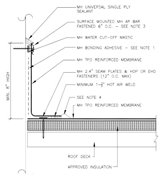
The NRCA recommends flashing heights of at least 8 inches above the finished roof membrane. In high-precipitation northern regions, 12 to 16 inches is suggested.
Create Adequate Rooftop Clearance
Inadequate rooftop clearances are a recipe for disaster. When penetrations through the roof are too close together or too near a wall, or when rooftop units are packed too tightly together, it is challenging for even an experienced, highly skilled professional to flash them properly. The result is poor flashings that will not pass inspection for the desired warranty, leading to costly and time-consuming change orders and repairs to get the warranty and prevent leaks and other problems.
Any penetration through the roof should be at least 12 “flashing inches” out from a parapet wall or roof edge, meaning there should be enough space between the penetration and the wall or roof edge to accommodate at least 12 inches of flashing.
Similarly, penetrations through the roof should be spaced at least 12 flashing inches apart to allow proper flashing.
Drains require additional room to accommodate their bell housings and clamping rings. All drains should be at least 24 flashing inches away from walls or roof penetrations and be spaced at least 24 inches apart.
HVAC units also need their space. When designing a roof with three or four small units, placing them on metal curbs attached to the membrane is acceptable. The contractor will be able to flash them correctly. But when there is a larger cluster of units, using metal or plastic platforms to elevate them 3 or 4 inches above the rooftop is a far more functional option. The pads can simply be placed on top of the membrane, with no flashing required.

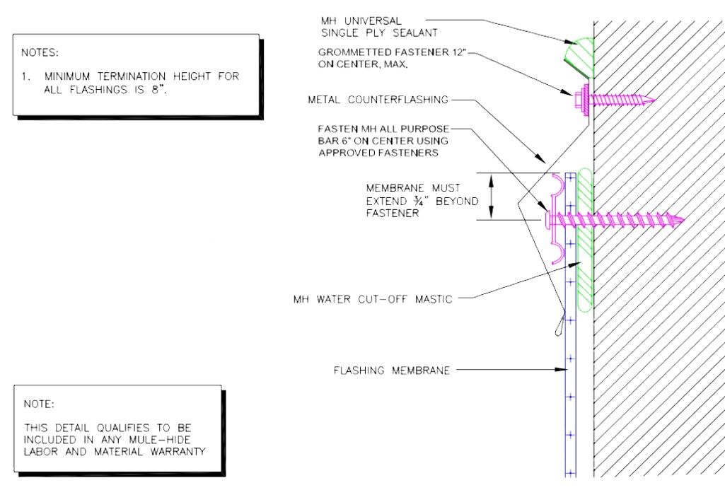
A termination bar is adequate for wall termination. Hower, a surface-mounted counterflashing will add additional protection from water infiltration and is aesthetically pleasing.
“Hot Stacks” Require TLC
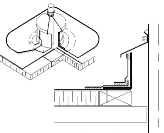
Flashing “hot stacks” that exhaust heat generated by machines operating below requires special attention. These stacks have the potential to create surface temperatures above 150 F and must, therefore, be treated differently from other types of projections to protect the roof membrane from heat-related damage.
The stacks must be spaced at least 12 flashing inches apart, at least 12 flashing inches from walls and roof edges, and at least 24 flashing inches from drains. No exceptions.
Uncured flashing membrane and non-reinforced membrane may not be used as wrap flashing.
The flashing membrane also must not be in direct contact with the stack. A metal sleeve with a larger diameter than the actual flue should be installed, creating an insulating air space to prevent overheating of the membrane. The detail is then made watertight by adding a storm collar that protects the air space from the elements.

An approved flashing detail for hot stacks.
Wall and Curb Flashing Heights
Designers also must allow for adequate flashing when setting elevations.
The National Roofing Contractors Association (NRCA) recommends flashing heights of at least 8 inches above the finished roof membrane. In high-precipitation northern regions, 12 to 16 inches above the finished roof membrane is suggested. When specifying tapered insulation, elevations should be checked using the maximum thickness used in the system.
Low-set clerestory windows can provide pleasing sightlines, and mechanical, electrical and HVAC engineers may have solid reasons for wanting wall penetrations in certain places. These elevations must, however, also account for the specified thickness of the roofing system. Failure to do so may cause the roofing system manufacturer to not approve the warranty. More important, it will jeopardize the long-term performance of the roof and the building.
Roof Edge Design
In a list of the most important considerations when designing a low-slope roof, the roof edge comes in second, behind only roof slope.
The majority of roof failures are the result of metal edge failures in high-wind events. The Roofing Industry Committee on Weather Issues Inc.’s 2007 report on wind-related roof damage caused by Hurricane Katrina backed this up, stating “Many examples of damage appeared to originate at failed edge details.” The report also offered the solution, saying “The main lesson learned appears to be that roofs designed and detailed according to current codes and standards will perform satisfactorily.”
Edge design is, therefore, not an area for cutting corners or pinching pennies.
Design professionals must not waver in requiring that all edge metal products meet ANSI/SPRI/FM 4435 ES-1 "Wind Test Design Standard for Edge Systems Used with Low Slope Roofing Systems” standards, and should specify that all are manufacturer-provided, pre-fabricated products. Roofing manufacturers’ system warranties exclude edge metal that does not carry the certification. If standard-compliant products are not used, the building owner will forgo that edge-to-edge protection, and if a blow-off occurs because the edge metal fails, the roofing manufacturer will not be responsible for repairing or replacing the membrane.
Continuous cleats, or clips, are required on faces with dimensions of 4 inches or greater, and the materials should be at least one standard gauge thicker than the exposed metal. This is the new standard, and all manufacturers offer such products.
Copings can make a big impact on a building’s aesthetics, but design professionals must remember that they are not waterproof. Waterproofing comes from the roofing membrane installed over the parapet wall. Shop-fabricated copings must be fastened on both the outside and inside of the wall, and these penetrations of the membrane are leaks waiting to happen. Instead, design professionals should protect the integrity of the membrane by specifying standard edge metal or by choosing snap-lock-style copings.
When covering exterior fascia, thicker metal should be used to prevent “oil-canning,” or a perceived waviness in the panel. The longer the span, the thicker the metal must be. That, of course, comes with a higher price tag. A more cost-effective option for longer spans is to use a combination of smaller face metals—24-gauge steel up to 8 inches long—and fascia extenders.
Conclusion
When it comes to delivering a high-performance, durable and warranty-eligible low-slope roof, success does indeed lie in the details. Sufficient drainage, protective edge metal and properly flashed penetrations are all crucial. Getting those details right starts during the design process. The time and thought invested will be well-rewarded in fewer change orders, a higher-quality and faster installation by the roofing contractor, and a happier building owner.


