Sponsored by GAF
CEU: At the Roof Edge: Water, Air, Thermal, and Vapor Control
"Out on the edge you see all the kinds of things you can't see from the center." - Kurt Vonnegut
LEARNING OBJECTIVES
After reading this article, you should be able to:
- Discuss the requirements to manage moisture, air, vapor and thermal continuity.
- Review code requirements and how to achieve compliance.
- Outline design and specification requirements to set achievable performance.
- Develop critical details blending form and function.
Complete the quiz and receive a certificate of completion
EARN: 1 AIA LU/HSW; 1 GBCI CE HOUR; 0.1 IACET CEU // AIA COURSE #BE2021A; GBCI COURSE #0920023799
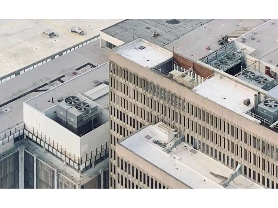
The parapet is so much more than the intersection of roof and wall. It’s also the junction where building aesthetics meets structural performance, air and moisture management, energy efficiency, construction trade sequencing and operational maintenance. Each of these perspectives is critical for the long-term performance of the building, but they are often at odds with one another. At such a critical interface, proper parapet detailing, installation coordination, and execution are paramount. Continuity of water, air, thermal and vapor control layers are necessary for long-term performance.
Types of Parapets
Parapets can be assembled in many configurations and each requires project-specific detailing. The 2018 International Building Code (IBC) defines a parapet as “the part of any wall entirely above the roofline.” To simplify the discussion a bit, this article will look at a baseline flush edge condition and two primary parapet types—platform framed and balloon framed—defined by how the roof and wall structure are connected.
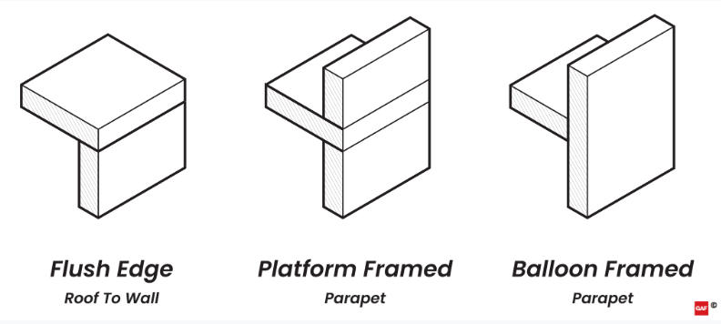
Caption: Flush edge roof-to-wall and two parapet configurations.
Parapets can generally be composed of structural materials such as wood framing, light gauge metal framing, pre-engineered steel, concrete or masonry. In this context, the terms “platform framed” and “balloon framed” are referring to the configuration of the wall and roof structure to form a parapet. These terms are applied to parapets throughout this article based on the parapet configuration and are inclusive of all materials comprising the assembly.
The flush edge roof-to-wall connection is the simplest approach, with the roof structure placed above the wall system. Compared to the platform or balloon framed parapets, the flush edge configuration provides the least wind uplift protection for the system at the roof edge and the most limited aesthetic options.
Platform framed parapets are similar to the flush edged construction, with the roof structure sitting directly on the wall system, but include a parapet wall assembly on top of the roof structure. In this configuration, the roof structure acts as a platform for the parapet wall above. Depending on the attachment method, height and materials of the parapet wall, additional lateral and/or wind bracing strategies may be needed for this type of parapet.
Balloon framed parapets are formed when the wall system bypasses the roof system to form a wall that extends above the roofline. In this configuration, the roof structure is commonly hung from the wall structure or supported by a separate superstructure inboard of the wall system.
Control Layer Continuity
To better understand common parapet challenges, it is important to review continuity across the roof and wall systems, specifically the key four control layers: water, air, thermal and vapor.
These four key control layers should generally be continuous across all six sides of the building enclosure. ASTM E2947 defines the term “building enclosure” to “refer collectively to materials, components, systems and assemblies intended to provide shelter and environmental separation between interior and exterior, or between two or more environmentally distinct interior spaces in a building or structure.” It is difficult—but not impossible—to achieve effective control layer continuity across the building systems, especially at significant transitions like a parapet or flush edge, where the roof system meets the wall system.
When beginning to think about designing the enclosure, it’s helpful to start with an ideal scenario. The configuration of the ideal wall system can be considered as follows: the cladding on the outside, continuous insulation keeping the rest of the control layers tempered in the middle, and structure to the inside. This “ideal” configuration can also be applied horizontally to the roof assembly. For the transition example, the roof and wall meet as an “ideal” flush edge with very simple transitions. As a system moves away from the ideal configurations, like with the inclusion of a parapet, wood blocking, or actual project constraints, the transition details become more challenging and trade-offs have to be made.
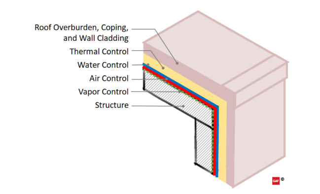
Caption: An “ideal” roof and wall transition.
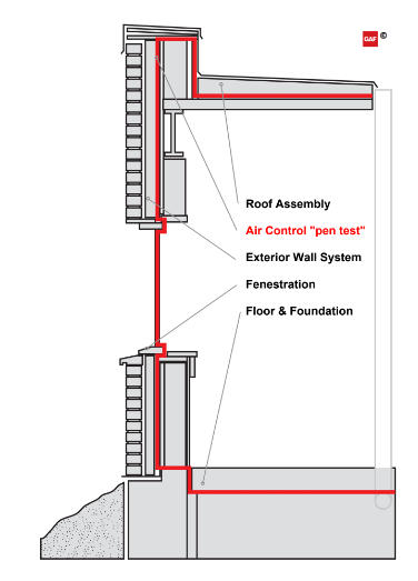
Caption: Example of air control “pen test” continuity across the building enclosure.
Water Control
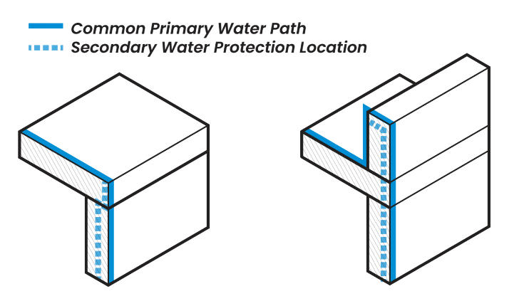
Caption: Water control diagram for flush roof edge (left), platform framed parapet (center), and balloon framed parapet (right).
Goal: Keeping water out of buildings is a function of both roofs and walls, so it’s reasonable to assume parapets and flush edges should do the same.
Principles: Construction-related moisture, installation deficiencies and damage in the use-phase can introduce moisture into the roof and wall systems. Construction acceptance testing, scheduled inspections and regular maintenance play an important role in ensuring the systems are able to meet their intended performance over time.
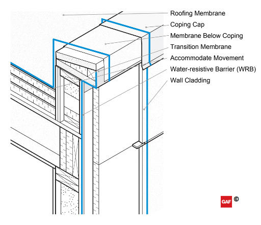
Caption: Water control elements highlighted in blue, an example of parapet continuity.
The figure above shows the individual components to be considered. In a parapet condition, it starts with managing the flow of water on the parapet coping cap which is sloped back to the roof system; this also helps prevent staining on the exterior wall. Where the roof membrane meets the parapet wall, the membrane should be installed to allow for the possibility of differential movement, and terminated with flashing/counterflashing under an appropriate transition membrane under the coping cap. Wall systems commonly include a secondary water management layer behind the exterior cladding. For instance, it is important to protect the top of the wall assembly with a membrane below the parapet cap, sealing fastener penetrations for coping cap cleats, and lapping over the wall’s secondary water management layer in shingle fashion.
A flush edge condition shares many similar considerations for bulk water management. Properly layering the edge components provides water-control redundancy and the metal edge provides a level of protection for the main water control layer. Wood blocking provides the support and fastening location for the edge of the field sheet and L-shaped metal edge. Concealed and fastened cleats or clips are installed so that they overlap and extend past the top edge of the exterior wall. The vertical face of the edge metal is secured by engaging the drip edge to the cleats. Splice plates, interlocked joints, or concealed sealant in the seams of the metal edge provide bulk water management where metal edge joints are visible. A membrane stripping ply is installed on top of the roof-side metal edge flange for bulk water control. A raised ‘gravel-stop’ metal edge keeps rain water on the roof side to drain properly, not down the exterior wall. An L-shaped metal edge allows bulk water to flow over it, ideally into a water management system (e.g., gutters and downspouts).
Air Control
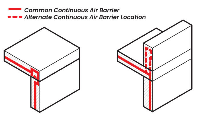
Caption: Air control diagram for flush roof edge (left), platform frames parapet (center), and balloon framed parapet (right).
Goal: Most buildings require a continuous air barrier. If you think of a building as a solid 3D shape, like a cube, then the air barrier must be continuously detailed across all six sides of the building enclosure to be effective.
Principles: To achieve continuity, the air control layer requires much more than selecting a material or specifying a lab-rated assembly. Air control discontinuities in parapets can lead to water ingress, impact occupant comfort, waste energy from loss of conditioned air, cause damage from significant condensation moisture, and transmit airborne contaminants through the building enclosure. The amount of moisture transported through the building enclosure via an air leakage pathway at normal interior-to-exterior pressure differences is many times greater than the amount of water vapor that can pass through a permeable material due to vapor diffusion alone. When it comes to the air control layer, parapets are among the most challenging areas to get right.
Roof membranes are generally very good at blocking airflow, but unless they are designed to be part of the continuous air barrier system, and tied into the other five sides, the building will still leak air.[1]
For low-slope roof systems, it can be beneficial to design the primary air control layer as the roof deck or to the topside of the roof deck. An example of this would be air sealing the penetrations to a concrete roof deck or installing a dedicated membrane to the roof deck, prior to installing insulation. Clearly identifying and communicating the air control layer in the roof system simplifies detailing at penetrations and transitioning at the parapet wall or flush edge.
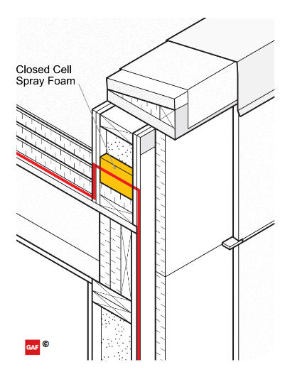
Caption: Air control elements highlighted in red, across parapet cavity example.
Installing an air barrier after the parapet wall is in place is difficult to get right. It requires significant coordination among trades to install the air control layer up and around the parapet wall, transition to the coping cap flashing, and terminate to the wall system air control on the other side of the wall. One alternative is to connect the air control layer from the roof side of the wall to the exterior wall by insulating within the wall cavity with a closed-cell spray foam. While this may be the “fussiest” option with regards to blocking, trade coordination and use of specialty trades, in some cases, such as balloon framed light-gauge stud walls, it may be the best (or only) option.
The case of a flush edge is fairly straightforward; maintain continuity of the air control layer either over or under the roof edge blocking and terminate over the wall air barrier system. The use of engineered transition membranes (pre-manufactured materials used to tie two (often dissimilar) air barrier materials together) at the roof-to-wall interface can accommodate the installation of incompatible materials. A transition membrane may also help resolve any scope-of-work issues between roofing contractors and wall air-barrier contractors as installation of an engineered transition membrane should be scoped early.
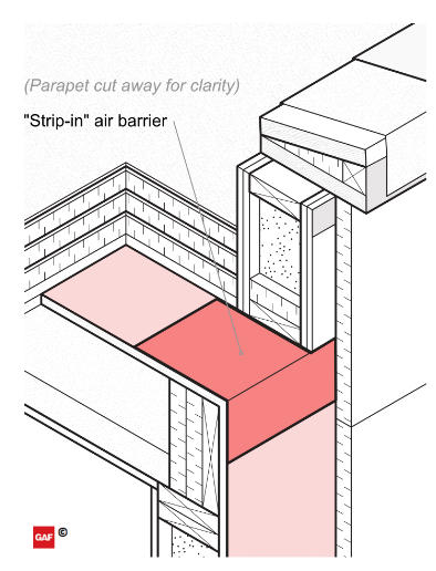
Caption: Air barrier “strip-in” example with platform framed parapet.
When the parapet wall is built on top of the roof deck, as in a platform framed parapet, it gets a bit trickier. The best option for continuity is to “strip-in” the air barrier to the roof deck before framing the parapet wall above the roof deck. Though the strip-in method is preferred as a way of keeping conditioned air out of the parapet, it requires significant trade coordination and is not often implemented in the field. To accomplish it successfully, the stripped-in portion of the air barrier should be installed with excess material on either side of the roof edge. Then frame the parapet wall on top of the roof deck, and connect the excess stripped-in membrane to the air control materials on the wall and at the roof deck.
Thermal Control
Caption: Thermal control diagram for flush roof edge (left), platform frames parapet (center), and balloon framed parapet (right).
Goal: Maintaining continuity of the insulation layer, especially the continuous exterior insulation, across the parapet is important to achieve the intended energy performance and to prevent moisture condensation on cold surfaces.
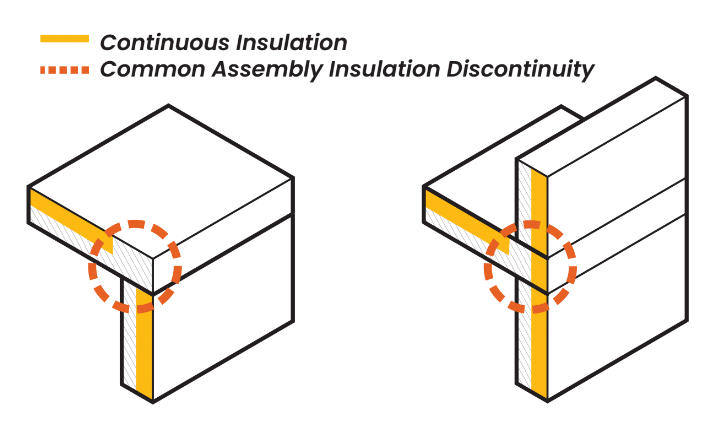
Principles: In current IECC and ASHRAE 90.1 national model commercial energy codes, the basic prescriptive requirements for both walls and roof systems include the use of continuous insulation in many climate zones and construction types. Continuous insulation is far more effective than cavity insulation, which is tucked into the voids between framing members. In parapets, the framing members are exposed to exterior conditions on both sides of the wall, rendering cavity insulation highly ineffective. Across the flush roof edge and parapets, maintaining continuity of the “continuous insulation” can be tricky. Even with continuous insulation designed in the roof and wall systems, a common thermal discontinuity emerges where the roof system meets the backside of the parapet wall. These discontinuities are important because they represent thermal bridges in the thermal control layer.
For the flush edge condition, the thermal discontinuity primarily results from the intersection of roof edge blocking for terminating the roof system and wall cladding at the transition. The compactness of this detail makes it difficult to simply add insulation. The roof edge blocking should be a wood-based material, which has a much lower thermal conductivity than steel. Using solid wood blocking (versus open steel components) also greatly reduces the potential for air movement at the transition from roof to wall that can reduce the overall thermal resistance at this location. Roof framing members over the wall below should be covered by the continuous insulation from the wall system below. That is, don’t stop the continuous insulation short of roof framing edge conditions!
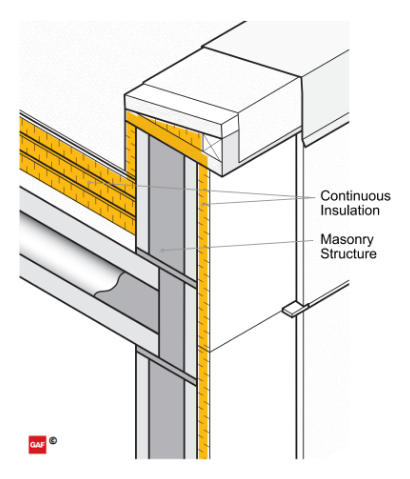
Caption: An example of thermal control continuity parapet.
For platform framed and balloon framed parapets, tactics for maintaining the thermal control layer may be specific to the wall framing material that extends past the roof. For walls composed of concrete, insulated precast, mass masonry or steel framing, the best approach may be to go up and over the wall with continuous insulation. In this case, continuous insulation is applied to the roof side of the parapet wall under the coping blocking at the top of the wall and connected to the continuous insulation on the exterior wall. If the parapet walls are tall cavity walls, this may not be ideal. Although insulated, the two-sided exposure and limited conditioning of the air in the cavity space within the parapet could still lead to condensation moisture on cold surfaces.
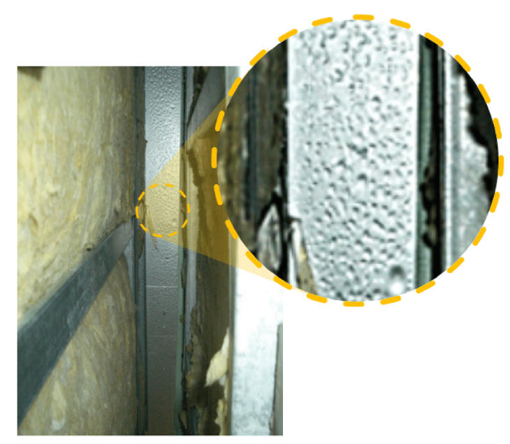
Caption: Looking up inside a balloon framed parapet. Condensation at the top of parapet from interior conditions. Image adapted from U.S. Environmental Protection Agency—Moisture Control Guidance for Building Design, Construction and Maintenance.
Another strategy that is better-suited for wood-framed and very tall steel-framed walls is to effectively, but not literally, extend the roof thermal control layer through the backside of the parapet cavity wall and connect on the other side to the exterior wall continuous insulation. This is similar to the strategy described in the Air Control section above, using closed-cell spray foam to connect the control layer from the roof side of the wall to the exterior wall within the wall cavity. As stated previously, this may still be the “fussiest” option. It is, however, well suited for wood-framed walls where thermal bridging is less pronounced than steel framing, and with tall steel-framed cavities where even continuously insulated, air-controlled parapets can result in condensation due to their exposure and isolation from the regular interior space conditioning. It is important to note that when insulating across the parapet wall cavity, air-permeable insulation like fiber batts is not effective. If interior air can bypass or travel through the insulation, it can still lead to condensation and moisture problems in the parapet above the air-permeable insulation.
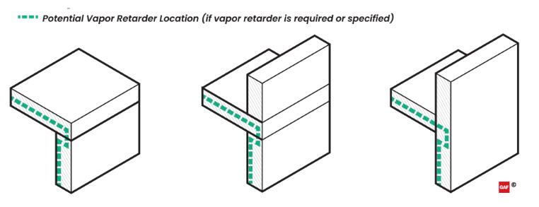
Caption: Vapor control diagram for flush roof edge (left), platform framed parapet (center), and balloon framed parapet (right).
Goal: The primary function of a dedicated vapor control layer is to prevent condensation that results from vapor diffusion. Vapor diffusion occurs when water molecules in the air (vapor) pass through a solid material due to a pressure differential (high to low) on either side of the material.
Principles: Vapor diffusion through a solid material, even a vapor-permeable one, is a slow process. There are specific scenarios where enough vapor is able to diffuse through a solid material (not carried along by air leakage) to result in significant moisture accumulation over time. (Think of all the moisture that can potentially accumulate in a roof system as a concrete roof slab cures.) When it comes to vapor control, it is also possible to cause moisture problems by adding a vapor impermeable material to an assembly, intentionally or unintentionally. All materials—from insulation to membranes, air barriers, sheet metal, sheathing boards, paint, adhesives and so on—have some level of vapor retarding properties. Be sure to consult with a building enclosure professional to understand what materials may act as a vapor retarder in the roof, wall and parapet assemblies.
Not all wall, roof and parapet scenarios require a vapor control layer. In fact, adding a vapor barrier to a design without consulting with a building enclosure professional can lead to unintended moisture problems, such as preventing an assembly from drying from incidental moisture. Many times when vapor control is discussed, the conversation quickly slips into “air control” strategies to manage condensation-related issues—as air movement can transport up to many times more moisture than vapor diffusion alone. Vapor-retarding materials (and vapor-open materials) often also act as air barriers and can be incorporated into the continuous air barrier design. As designing and installing continuous air barriers becomes required in most buildings, the confusion regarding air barriers and vapor retarders still exists.[2]
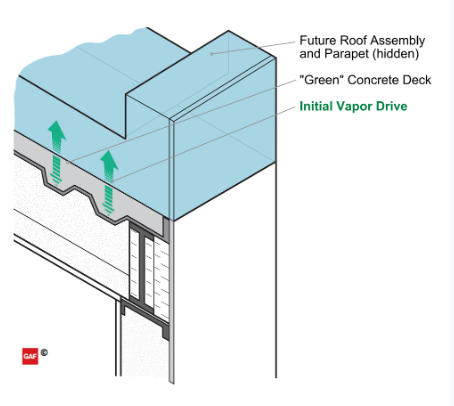
Caption: Initial concrete roof deck moisture example.
For parapets, flush edges, and roof systems in general, one of the more challenging vapor control scenarios involves newly poured or “green” concrete roof decks. Significant initial moisture within the concrete will diffuse into the rest of the system or interior (due to its high vapor pressure) over a potentially long time. If the concrete is placed on a steel composite deck and can’t dry downward through the steel, then moisture in the concrete will drive to the exterior (upward) through the roof system, wetting the roof system along the way. A common strategy is to install a Class I or lower vapor retarder on the top surface of the concrete deck to prevent the moisture from rising. However, a self-adhered vapor retarding material may not always stick to high-moisture concrete. If a vapor barrier is to be installed above the composite concrete deck, a vented steel composite deck may be somewhat helpful as a means to provide a path for downward drying of the concrete, but this is not a definitive solution. Alternatively, an above-deck vapor retarder that allows horizontal movement of moisture with perimeter venting (think insulating lightweight concrete roof design) may also be beneficial.
Control Layer Summary
Discussing control layers as they apply to a roof or wall alone is fairly manageable. But the process gets much more complicated when the roof meets the wall at the parapet condition, and even at a flush edge condition. The “pen test” is relatively easy in theory, but it can get complicated as we zoom in and consider the control layers at each condition, penetration and transition.
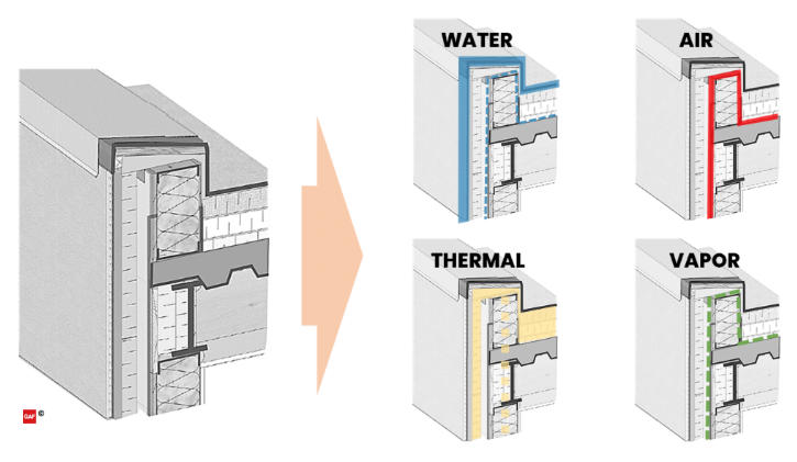
Caption: Example of breaking down a parapet detail by the four control layers.
In summary, the following are key points to maintain continuity of the control layers:
- Water Control is managed by the roof membrane and the cladding. A secondary water control layer is often found against the structure, behind or below the exterior insulation.
- Air Control can be managed at the deck level of the roof, which more readily can be married into the wall air barrier. The roof membrane can also be used as an air barrier as long as the detailing and transitions are done carefully.
- Thermal Control continuity is maintained by connecting the roof and wall insulation, which can be challenging. It’s important to be mindful of cavity insulation and the potential design risks of condensation at the thermal bridges.
- Vapor Control can also be in the same plane as the air control layer, based on location needs, construction methodologies and occupant use of the building.
Code References for Parapets
This section will make reference to the following national model codes and standards: 2018 International Building Code (IBC), the 2018 International Energy Efficiency Code (IECC), and the ANSI/ASHRAE/IES Standard 90.1-2016 (ASHRAE 90.1). It is worth noting that the summary provided below is not an exhaustive list of requirements for exterior wall and roof systems in the referenced national model building and energy codes. Different versions of the referenced codes have additional and/or different requirements; these requirements may also vary by adoption and modification by the local authority having jurisdiction. It is important to refer to local codes for the applicable requirements.
The requirements for parapets generally come from the building code (IBC) and the energy code (IECC and ASHRAE 90.1). The requirements within the building and energy codes can be mandated prescriptively, as a performance threshold, or by reference through specific key standards. The performance standards are important because they don’t attempt to regulate by providing exhaustive lists and itemized component requirements, like a prescriptive method. These performance requirements establish the design benchmark and then provide a methodology to demonstrate compliance with the benchmark.
The building codes and standards do not always address parapets exclusively, but many refer to “Exterior Walls” separately from “Roof Assemblies.”
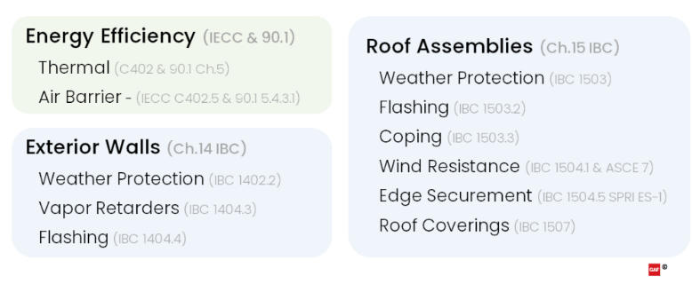
Caption: Summarized applicable code references for parapets.
Exterior Envelopes in the Building Code
The exterior wall requirements for parapets are covered in Chapter 14 of the IBC which addresses “exterior walls, wall coverings and components.” For parapets, the requirements for weather protection, water-resistive barriers (WRBs), managing vapor and flashing apply as they do for the rest of the exterior building walls.
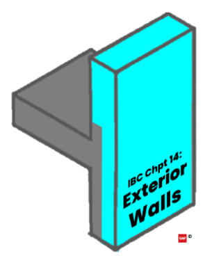
Caption: IBC Chapter 14: Exterior Wall applicable area highlighted in blue.
The roofing portion for parapets is covered in Chapter 15 of the IBC which addresses roof assemblies, specifically the “design, materials, construction and quality” of roofs. Regarding parapets, the roof system requirements impact the wall where terminations and transitions occur. The requirements include weather protection, flashing, coping, wind resistance design, edge securement and specific requirements for various types of roof coverings.
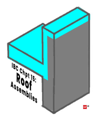
Caption: IBC Chapter 15: Roof assembly applicable area highlighted in blue.
Roof Assembly Weather Protection: The requirements for weather protection (IBC 1503) are fairly broad, requiring roof decks covered with approved roof coverings. Much more detail is covered in the additional IBC sections regarding roofing and parapets. In the roofing provisions, it is important to note that compliance with “the manufacturer’s approved instructions” doesn’t just affect a project’s eligibility for warranty, but is also required for building code compliance.
Roof Assembly Flashing: The requirements for flashing (IBC 1503.2) are repeated in part across the wall and roof portions of the code. This repetition highlights the importance of managing water control at the transitions. The code requirements for both roofs and walls support the water control layer principles in the pen test discussed previously. The roofing chapter in the code also directly mentions the parapet walls as a critical location for both roof system transition flashing and requirements for copings. While not an exhaustive list, IBC 1503.2 includes a minimum list of areas requiring roof flashing. These are summarized below:
- Flashing joints in copings
- At moisture-permeable materials
- At intersections with parapet walls
- At other penetrations through the roof plane
Roof Assembly Coping: The roof requirements for parapet wall copings are spread across many categories. One section specific to copings (IBC 1503.3) has a limited scope, requiring materials to be limited to “noncombustible, weatherproof materials” and be installed with a “width not less than the thickness of the parapet wall.” Many other requirements in the code also apply to copings in the code, such as flashing, wind design loads and edge securement performance. More will be discussed about copings in those sections.
Roof Wind Resistance: The wind resistance for low-slope commercial roof decks and roof coverings (IBC 1504.1) is required to be designed in accordance with IBC 1609.5, which ultimately leads to utilizing ASCE 7 for determining design wind loads. There are numerous updates to ASCE 7—2005, 2010 or 2016—and each has its own nuance as to how it impacts roof design loads.[3] Because ASCE 7 is a performance standard, it is possible to use a version with higher performance requirements because designs do not need to be the minimum allowance.
ASCE 7-16 design wind loads are generally increasing relative to ASCE 7-10. In a recent blog article that reviews the analysis of two buildings of different sizes in two different cities, the author illustrates that design wind loads are reduced in Roof Zone 1' while Roof Zones 1, 2, and 3 have increased design wind loads. Roof Zone 1 percent increases are greatest while Roof Zone 3 increases are smallest. The increases in Pressure Coefficients from ASCE 7-10 to 7-16 are, in fact, relatively indicative of the increases in the design wind loads.
The methodology for determining the size of the perimeter and corner roof zones has also changed significantly in the new ASCE 7-16 version, resulting in larger roof areas contained by the perimeter and corner roof zones. Increased wind loads and larger perimeter and corner roof zones means that a greater area of the roof requires a higher capacity roof system and inherently more fasteners are used to secure the roof to the building. The referenced blog article provides an example where a 5-story building in Kansas City, Missouri requires nearly the entire roof system to have a higher capacity when calculating design wind loads using ASCE 7-16 vs. ASCE 7-10.
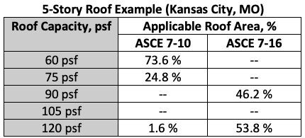
Caption: Chart showing required roof capacity and the roof area (%) where each is required.
Parapets are a combination of wall and roof pressures. The exact height of the parapet is not factored into the roof wind uplift calculations, but if the parapet is 3 feet or higher, the perimeter values can be used at the corners, lowering the uplift requirements for that portion of the roof area.
Continuing with the example 5-story building in Kansas City with the roof capacity shown in Figure #18, the use of a 3’ continuous parapet would eliminate the need for the 120 psf capacity system and the entire roof could be designed and installed with a 90 psf capacity roof system. This approach would meet the code design requirements, simplify installation, and reduce the square foot cost of the roof, just by installing a 3’ continuous parapet.
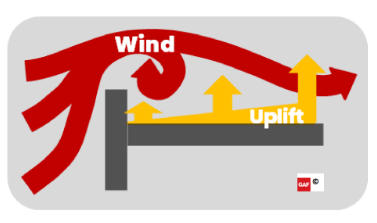
Caption: Parapets can help reduce wind uplift at the corners and perimeter.
Roof Edge Securement: Securing the edges on low-slope roofs (IBC 1504.5) has a significant impact on preventing failure and allowing the roof system to resist loads as it was designed. In addition to designing the wind resistance performance for the entire building (i.e., walls, roofs and parapets) per ASCE 7, metal roof edges are required to be tested for resistance in accordance with Test Methods RE-1, RE-2 and RE-3 of ANSI/SPRI ES-1. The referenced standard ANSI/SPRI ES-1 is a performance requirement that is specific to the strength of metal roof edges.[4] ES-1 covers the “baseline” flush roof edge as well as parapet coping caps. When designing, it is important to specify compliance with ES-1 in the construction documents.
Roof Coverings: The IBC provides minimum installation criteria (IBC 1507) for various roof systems, based specifically on the attributes of that roof covering. In addition to the prescriptive criteria listed within, the IBC also mandates that “roof coverings shall be applied in accordance with the… manufacturer’s installation instructions.” Generally, the content of these roof covering sections address minimum substrate requirements, minimum roof slope, ballast requirements, and relative ASTM references to material standards, such as D6878 Standard Specification for Thermoplastic Polyolefin (TPO) Based Sheet Roofing.
Energy Efficiency for Parapets
Generally, within the IBC it is required that a building be “designed and constructed in accordance with the IECC 1301.1.1.” The IECC has both residential and commercial provisions, and the commercial provisions apply to “all buildings except for residential buildings 3 stories or less in height.” The IECC is structured in a way that provides the option of either complying with the prescriptive requirements within it or by complying with the alternate ASHRAE 90.1 energy standard.
Compliance Alternatives: The IECC has multiple compliance paths within it, including:
- Either following the prescriptive requirements within the IECC or ASHRAE 90.1, or
- Following the performance modeling requirements of ASHRAE 90.1 Appendix G.
The prescriptive options within both the IECC and the reference standard ASHRAE 90.1 primarily regulate energy use by providing lists and itemized requirements. These can be helpful when the building is straightforward and tradeoffs don’t need to be made. When a building is more complex, has specific energy usage demands, or if an owner wants to demonstrate energy compliance beyond code, the performance path within ASHRAE 90.1 Appendix G is the methodology required. For example, any modeling being performed to show compliance with LEED is being performed to comply with Appendix G in ASHRAE 90.1. A growing method of compliance is whole-building design energy modeling and on-site performance testing happening in new construction. When an existing building is reroofed, the designer will most likely follow the prescriptive path to determine the amount of insulation to use.
Code Summary
For the various applicable codes and standards, in both roofs and walls, weather protection and flashing are important requirements at all transitions and penetrations, including parapet conditions. It is vital to specify key reference standards for wind and edge securement, in order to achieve the performance needed to keep the roof on the building as intended.
In general, the energy codes require continuity of the thermal and air control layers. Detailing the thermal control and air barriers to be continuous in the design AND field installation are critical for energy code compliance.
While the building and energy codes do not require consideration of a reduction in effective R-value, there are unintended consequences in terms of energy efficiency when increasing the number of fasteners in the roof system that should be considered. This article takes a closer look at attachment options and considerations to meet uplift requirements while considering the thermal impacts of the design.
Coordinating Complexity
This section provides a practical example of applying the control layer continuity principles and working through how the construction trade sequencing could flow as a result. This example is intended to demonstrate some common challenges. When confronted with a similar design as the example below, a general contractor may request alterations to the design in order to shorten the schedule or reduce costs. However, this value engineering process—the reduction of cost and time—may also comprise continuity of the control layers and reduce the intended long-term performance of the parapet systems.[6] If unsure or designing high-performance buildings, it is recommended to engage a building enclosure consultant to help anticipate continuity and constructability issues.
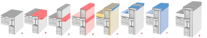
For the purposes of this discussion, the materials applied to the parapet assembly sequence (Figures A-H below) are color-coded in their application step by their primary control layer function:
- Water control elements are shown in blue
- Air control elements are shown in red
- Thermal control elements are shown in yellow
- Vapor control elements are not shown separately (See the Vapor Control section above for applicability)
To help identify separate materials within a control layer, lighter and darker versions of the color are used to distinguish elements within the same step. Also dashed, or “hidden lines,” are used to depict materials edges that may be overlapped or behind another layer in the sequence the same step.
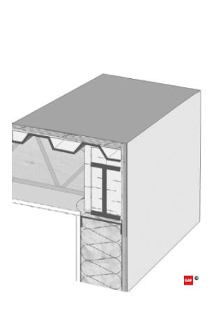
Caption: (Figure A) Initial condition.
a. In the initial condition, the wall and roof deck are assembled up to their sheathing. The roof structure is a corrugated steel deck with a substrate board placed on top to provide a continuous surface for later air barrier adhesion. The exterior wall is steel framed with cavity insulation and exterior sheathing applied.
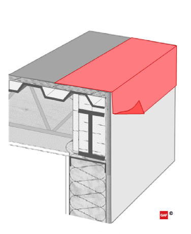
Caption: (Figure B) Pre-treated corner.
b: In preparation for the parapet wall construction, a strip of air barrier material is applied to the roof and wall edge with sufficient material for future integration with the remainder of the continuous air barrier. It is important to note the material on the wall side is not yet adhered to allow for future lapping to manage water in “shingle fashion” as required by the IBC. This can be accomplished by leaving a portion of the release liner in place for adhered materials.
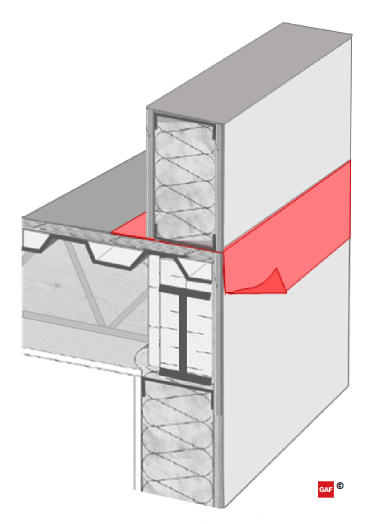
Caption: (Figure D) Air barrier integrated.
d: After the parapet wall is in place, the remainder of the continuous air barrier can be applied to both the roof and wall systems. It is notable that if the air control layer is also intended to act as the WRB in the wall and parapet system (as shown in Figure D), the application should start from the lowest point and work upward; this allows the subsequent layers to be lapped in shingle fashion. After the air barrier is applied to the walls (light red), the pre-applied strip of material can be lapped and secured over it (dark red in the center of the wall). The air barrier can then be applied to the roof deck (light red), up the backside and over the top of the parapet wall, and then terminate downward on the outside of the wall, lapping over in shingle fashion (dark red at the top of the wall). Lapped edges hidden behind the layers of air barrier materials are shown with dashed lines.
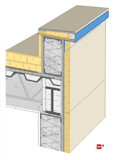
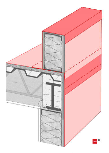
Caption: (Figure E) Continuous insulation installed.
e: The roof insulation and high-density coverboard can now be installed to the roof deck. These could be mechanically-fastened or adhered roof systems, but the use of mechanical fasteners through the entire roof insulation can have a significant effect on the thermal performance of the building. [7] Continuous insulation is also applied to the backside of the parapet wall to maintain continuity. The parapet blocking for the coping cap can now be installed. In this case, it also includes a layer of tapered insulation to provide slope back to the roof area and extend the continuous insulation to the top side of the parapet. Wood blocking is included as required to accomplish fastening to meet ANSI/SPRI ES-1 uplift requirements. After the parapet blocking is in place, a piece of counter flashing (shown in blue) is required to lap over the WRB prior to the installation of the walls continuous exterior insulation; flashing will later lap over the coping cap, but without this piece pre-installed, there would be a discontinuity in the water control layer. The bottom edge of the flashing, under the wall exterior insulation, is shown as a dashed line.
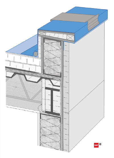
Caption: (Figure F) Roofing and terminations installed.
f: The roof membrane is applied to the roof area. An expansion joint may also be added at the joint between the roof and the parapet wall to allow for any expected movement between the systems. The membrane is then lapped and seams completed at the horizontal roof edge, extended up the backside of the parapet wall and terminated over the previously installed counter flashing on the face of the coping blocking. Terminating and lapping downward on the outside of the parapet wall maintains the continuity of the water control layer and provides a shingle-lap onto the secondary water control layer on the wall. The membrane over the coping blocking will also act as a secondary protection below the future coping cap. The coping cap attachment cleats and spline flashing are installed to the top edge of the parapet wall, bedding and treating the fasteners in sealant where they penetrate the membrane.
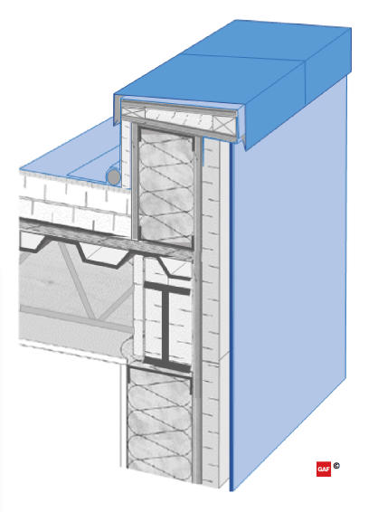
Caption: (Figure G) Coping and cladding installed.
g: The exterior cladding is then installed to the outside of the parapet and exterior walls (light blue). The coping cap is installed at the top of the wall, over the cleats and blocking (dark blue). The coping cap should be attached with the cleats as tested for by ASNI/SPRI ES-1, lapped over the cladding with drip edges on both sides, and maintain an overall slope towards the roof system to shed water.
Enabling Success
Identifying and maintaining continuity of the four key control layers is important in the design phase. To get the design intent implemented in the field, detailing and identification of the control layer(s) in the drawings and specifications is critical. This can require the design to be pretty specific—more than just “or equal” or “by others.” Specifying materials with known compatibility is important. And if the sequencing of components and members in the field impacts the intended continuity or performance of the control layer in the design—it should be addressed.
These challenges should be considered for every project. Standard details aren’t able to capture project complexities such as high-to-low parapet transitions, terminations into a rising wall and curtain wall flybys. These conditions all require unique detailing that must include continuous and well-conceived transitions. It’s important to remember that control layer discontinuities can lead to failures in the field. For instance, air leakage can lead to concealed condensation, which can be mistaken for roof leaks.
Complexity is Common
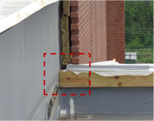
Caption: Common complexity at parapet-to-wall interface.
Parapet assemblies include numerous components and accessories. That often results in complicated interfaces even before reviewing design-specific conditions. Critical detail locations are often difficult to illustrate on 2D drawings alone and can require exploded diagrams and/or sequence information to communicate the design intent. Additional complexity is common for parapets at the following locations:
- Parapet wall terminating into an adjacent building wall
- Height or material changes of the parapet wall
- Parapet with cladding on both sides of the wall system
- Eave and soffit conditions extending past the exterior wall face
- Curtain walls extending beyond the roofline
- Inside/outside corners of parapet walls
- Scuppers and other penetrations
Engaging a building enclosure professional and selecting products with details and field support to assist in maintaining the four key control layers (water, air, thermal and vapor) is critical to achieving the optimal performance of the building enclosure.
Coordination is Key
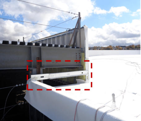
Caption: End wall not assembled at parapet termination.
The project design and details should consider construction sequencing, access and replacement across the expected life of the building. The framing contractor, for example, should be allowed to complete the construction of the primary framing before beginning the installation of the air barrier components. Sequencing the work of different trades makes it easier to coordinate air barrier installation. Sometimes it’s necessary for one trade to pause one phase of work in order to pre-treat a critical interface before proceeding (e.g. “pre-stripping” the roof joint at a platform framed parapet wall.) Early, clear and frequent communication helps to keep everyone on the same page. The following are best practices for enabling communication between the owner, general contractor, trade contractor, architect, building enclosure professional and performance testing agency:
Prior to Construction
- Meet with design team, contractor and affected sub-trades to discuss control layer continuity strategy and details.
- Affirm the expected service life of the building and systems installed in conjunction with the control layers.
- Make final material selections and confirm compatibility of substrates and accessories across roof and wall systems.
- Confirm requirements for manufacturer warranties and/or guarantees across wall and roof systems.
- Confirm sequencing and mobilization expectations across trades. Who goes first? Who has to come back?
- Discuss the quality control and quality assurance procedures during installation.
- Prepare mock-up(s) demonstrating the parapet details.
During Construction
- Weather and overnight protection during on-site parapet assembly.
- Consult product literature prior to use of all roof and wall products to ensure instructions are followed at parapets.
- Install control layer pre-stripping, blocking, and accessories, as required, at penetrations, details, and interfaces to maintain continuity.
- Minimize “blind” attachment through exterior finishes into the structure and sheathing.
- Involve manufacturer or certified professionals, as required, to establish warranty and/or guarantee requirements.
- Notify enclosure professional when air barrier details are ready for review, which may include the roof vapor retarder or roof membrane.
- Perform qualitative and/or quantitative testing to verify water and air control performance and identify air leakage locations; document any resulting design changes.
After Occupancy
- Document and communicate critical continuity details for maintenance and replacement in the future.
- This includes methods for maintaining air barrier continuity upon replacement when the roof membrane is designed as part of the continuous air barrier, and/or conditions where “hidden” elements like closed-cell spray foam in the parapet assembly are integral to the performance of future replacements.
Perform, schedule and document regular inspections, maintenance, and repairs of the parapet conditions.
References
1. How Air Barriers and Low-Slope Roofing Can Work Together, http://blog.gaf.com/how-air-barriers-and-low-slope-roofing-can-work-together/
2, 5Air Barriers versus Vapor Retarders, http://blog.gaf.com/air-barriers-vs-vapor-retarders/
3An Analysis of Wind Load Design—Load Side, http://blog.gaf.com/analysis-wind-load-design-load-side/
4The Details Make the Difference in Wind Design, http://blog.gaf.com/details-make-difference-wind-design/
6Value Engineering—Optimizing Performance or Reducing Costs?, http://blog.gaf.com/value-engineering-optimizing-performance-or-reducing-costs/
7R-Value Optimization: A Case Study, http://blog.gaf.com/r-value-optimization-a-case-study/
Complete the quiz and receive a certificate of completion
EARN: 1.5 AIA LU/HSW; 0.1 IACET CEU // AIA COURSE #BE2020A
Looking for a reprint of this article?
From high-res PDFs to custom plaques, order your copy today!
.webp?height=740&t=1767036885&width=auto "Header - BE 1170x658 (002).png")

.webp?height=740&t=1755781744&width=auto "KEE(2).png")

