Permeability and Performance in Water-Resistive Barriers
Identifying the Proper Choice for Applications

Contrary to popular belief, building codes do allow for use of permeable water-resistive barriers (WRBs) in cold climates. In fact, high-perm water-resistive barriers may actually be preferable in many cold-climate applications.
Abstract
The topic of WRB permeability in a building assembly is wrought with confusion. The design principles make the topic sound simple—prevent moisture issues by ensuring the building envelope manages moisture and the movement of air throughout the building, and allow for moisture in the assembly to drain away or evaporate—but the science behind it can quickly get technical and confusing.
Generalizations and misconceptions about accomplishing these principles are perpetuated based on practices that have lagged behind advancements in understanding the movement of water vapor through a wall assembly, inaccurate application of dew point analysis, and a misunderstanding of the differences in application of vapor retarders, vapor barriers, water-resistive barriers and air barriers. The complexity caused by air carrying moisture is a factor in the correct application of envelope components fighting moisture intrusion.
This has led to the common misunderstanding that code only allows for the use of in cold climate zones, which is not the case. In this white paper, we’ll address why code allows both high- and low-perm WRBs, with proper selection depending on the other materials used within the wall assembly. We’ll present how understanding code* requirements and optimal wall assembly.
For the purposes of this white paper, WRBs above 10 perms, when tested per ASTME96 Procedure B
(wet cup), are classified as high permeability. WRBs less than 10 perms (wet cup) are classified as low permeability.
Water’s Three Invasive Forms
Determining the appropriate degree of permeability in the assembly begins with an understanding of the forms of water that the assembly confronts.
Liquid – Gravity and wind can pull rainwater, groundwater, and melting snow into the envelope, but so can surface tension, capillary action and differences in air pressure.
Vapor – Water in a gaseous form that exists in the air both inside the building and outside of the building can diffuse through the building envelope through differential vapor pressure.
Solid – Moisture can condense and freeze within the envelope, compromising its integrity through the contraction and expansion that occurs when ice thaws, returns to liquid water, and refreezes again.
Follow the Three D’s: Deflect, Drain, Dry
Good water management can be achieved by following three basic principles: deflect, drain, and dry. No matter how hard you try to avoid water infiltrating your structure, it’s just a matter of when it will get in and to what degree. But the rule still stands: deflect water wherever possible. When water can’t be deflected, drain as much of it away from the building envelope assembly as possible. For any water that does get into the building envelope assembly, create as much ability for fast drying as possible.
Strategy One: Deflect
Inevitably, all buildings will eventually leak due to the natural movement and degradation of materials over time. Cladding serves as the first defensive protocol against the most significant cause of building envelope deterioration—driving rain. It acts as the primary plane of deflection. A variety of cladding systems exist.
Sandwich panels are impervious to rain. Through the tongue and groove connecting of the impermeable metal panels, water, vapor and air barriers are achieved.1
Curtain walls are comprised of aluminum frames with infill panels, glazed or opaque, which are fixed to the frames. While aesthetically pleasing, water infiltration, condensation and air leakage can occur and in cold climates, condensation can occur and ice can form.2
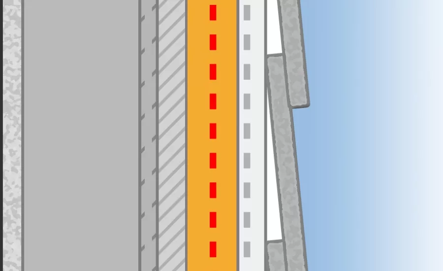
But where primary deflection fails, secondary water-resistive barriers help to manage liquid water concerns by stopping water from moving deeper into the wall assembly. Rainscreens are a component of double-wall construction.3 While some water will find its way into the cavity, direct rain is deflected and the wall is protected from significant amounts of water. The inner part of the wall assembly provides the airtightness, structural stability and the thermal insulation.4
Good design practice further protects buildings when proper flashing and channels for drainage are included and permeability of the WRB is optimized for drying. This is where water-resistive and air-resistive barriers come crucially into play to avoid mold, mildew, corrosion, decay, and other issues that can cause critical damage to building structures and human health. A variety of tools are available to help prevent damage from water that passes the primary weather barrier in its different forms.
Strategy Two: Drain
Liquid water in the assembly needs to be able to drain to the exterior of the building. A number of cladding types, such as stucco, wood, fiber cement, concrete and masonry absorb water and become, as Building Science Corp. refers to them, reservoir claddings. Absorbed water is transported by capillary action. Keeping water from the wall assembly begins with controlling that capillary action in the cladding, which is the function of a drainage plane, along with ample space between the reservoir cladding and the wall assembly.
An air barrier inwardly placed from the cladding can function as the drainage plane if it is continuously sealed. When absorbed water is exposed to the sun’s heat, the water turns to vapor, and serious inward vapor drive occurs—even in warm climates.5 Drainage cavities formed by drainage mats and channels can help facilitate this action. Vapor drive occurs in an assembly when pressure differentials between the inside and the outside of the building cause moisture-laden vapor to move from an area of high pressure to an area of low pressure where cooler, drier air is present. Pressure differentials are only a consideration for the assembly if the materials have the permeability to allow for vapor diffusion, where vapor molecules pass through porous materials. The rates of vapor diffusion are dependent upon the degree of permeability. Although it has often been considered a negative occurrence for the envelope, vapor diffusion can actually perform an important drying function and should be considered a necessary component for proper assembly design.
Strategy Three: Dry
As water heats, the vapor particles are able to travel through much smaller openings in the wall assembly. Creating the ability for that vapor to escape the assembly becomes crucial to long-term building endurance, regardless of the locale and climate outside.
Cooling air becomes less able to hold moisture, raising relative humidity as water vapor density falls. At 100% relative humidity, the air is saturated in moisture, condensing into dew droplets that can form on the surface of the assembly. Whether condensation occurs within the wall assembly is a function of the temperature of the wall components. In a cold winter climate, for example, the indoor temperature is likely around 70º F degrees while the outside temperature may be 10 degrees Fahrenheit. Based on the wall assembly components, the temperature of the sheathing may be at the dew point, where moisture-laden air condenses as water droplets. When components such as continuous insulation are added, outbound of the exterior sheathing, the location within the assembly where dew point temperature is reached may also be moved outbound of the sheathing. In this scenario, a vapor permeable WRB may allow water vapor to be carried beyond the secondary water barrier and, assuming a drainage cavity is in place, allow for liquid water to form where it can be safely drained out of the assembly.
Complexity in building envelope design occurs because the dew point is variable depending on atmospheric pressure and temperature, as well as the variance in the assembly components and their temperature throughout the building. This results in variances in the temperature of the wall assembly components. Condensation can occur on any of the assembly components, driving consideration of material usage with vapor diffusion capabilities as a means of moisture management. Understanding this dew point analysis plays a vital role in successfully designing and constructing new buildings and assessing the state of existing ones.
When water condenses on a building’s exposed internal surfaces (like cold windows), this is called surface condensation. When it occurs within the fabric of the building (such as on the surfaces of assembly materials), it is called interstitial condensation, which can cause mold and other moisture-related issues. Historically in cold climates, a vapor retarder was installed on top of the sheathing to prevent vapor diffusion from the exterior to the interior. This, however, results in potential condensation from the warm, moist interior air in high pressure toward the cold, dry exterior air in low-pressure. The warm, moist air cannot escape, causing condensation to occur on the inward-facing side of the sheathing.
Conversely, when the weather is warm outside, placing a vapor retarder on interior side of the sheathing restricts the movement of warm, moist outside air in high pressure toward the cool, dry low pressure air inside the building, causing condensation to form on the outwardly facing side of the sheathing.
The natural response to this is to assume placing a vapor retarder on both sides of the sheathing will solve the dilemma; however, this only restricts moisture-laden vapor from escaping the building in both directions. Water vapor needs to escape for the assembly to remain dry. It can move inside or outside to dry, or the location where dew point is reached must be strategically located so when liquid water forms it can drain out and away from the building. In freezing conditions when ice forms on the wall, the concern is that melting water can leak into the building materials as the water droplets heat up and expand. Warmer temperatures inside create opportunities for condensation to evaporate.
Building Code Requirements
Industry nomenclature has contributed to confusion about materials application. The lowest permeability occurs in a vapor retarder that has a permeance rating of 0.1 perm or less referred to as a vapor barrier. Vapor retarder permeance ratings can range from 0.1 perm through up to 10 perms. Such vapor retardant materials come in a range of products, including gypsum mats, asphalt saturated building papers, oil- or latex-based paints, elastometric coating, vinyl wall coverings, or sometimes a combination of these materials. Water-resistive barriers resist liquid water from entering the building envelope, while air barriers prevent the uncontrolled flow of air. Some products may act as both water-resistive barriers and air barriers, and in some cases a single product may act as a water-resistive barrier, air barrier, and vapor retarder. Unfortunately, because multiple functions may be performed by single components, confusion has arisen about how to label these products leading to improper naming and even improper understanding of the functions of these components. As an example, it is not uncommon for an “air and vapor barrier” to be referenced when the design professional is actually describing an “air and water-resistive barrier.”
Depending on the various materials used within the wall assembly, code allows for both high- and low-perm WRBs, with proper selection depending on the climate zone, type of building, and other materials used within the wall assembly. Understanding code and vapor drive dynamics reveals that, often, a vapor-permeable WRB is a preferable choice, provided that the rest of the wall assembly addresses issues of air-tightness and liquid water penetration.
The IBC states:
• Exterior walls shall provide the building with a water-resistant exterior wall envelope.6 This envelope shall include flashing.
• The exterior wall envelope shall be designed and constructed in such a manner as to prevent the accumulation of water within the wall assembly by providing a water-resistive barrier behind the exterior veneer, and a means of draining water that enters the assembly to the exterior.
• Not fewer than 1 layer of No. 15 asphalt felt, complying with ASTM D226 for type 1 felt or other approved materials, shall be attached to the studs or sheathing, in such a manner as to provide a continuous water-resistive barrier behind the exterior veneer.
It’s worth noting that the code says asphalt felt, or another approved substitute must be used with flashing to keep water outside the sheathing. The International Code Council Evaluation Service (ICC-ES) has evaluated a number of WRB materials for use as a substitute for No. 15 asphalt felt, including but not limited to building wraps, liquid-applied WRBs, Grade D building paper, and certain wall components incorporating rigid foam insulation. Building papers and asphalt felt have a permeability of approximately 30 perms (wet cup). With this level of permeability, the asphalt felt will shed water and allow for drying to the exterior but will not likely be able to serve as the vapor retarder.
The Role of Climate
Climate doesn’t entirely dictate WRB choice, but it does play a major role. Analyzing the temperature profile of the varying wall components for specific indoor and outdoor conditions for the building determines the use of specific materials. For example, determining the dew point of a wall configuration informs where you can expect condensation to occur.
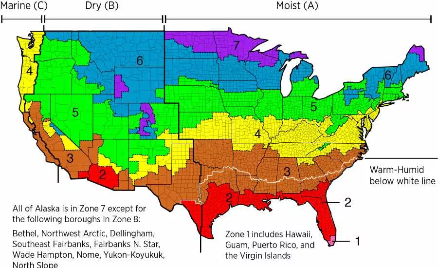
The IBC’s requirements for exterior walls address different needs for different climate zones, dividing vapor retarders into 3 classes (Section 1404.3 –Vapor Retarders):
Class I: 0.1 perm or less (e.g. PE film)
Class II: 0.1 > perm _ 1.0 perm (e.g. oil-based paints)
Class III: 1.0 > perm _10 perm (e.g. water-based paints, other materials)
Class I or II vapor retarders (less than 1 perm) are required in cold climates (climate zones 5 through 8 and Marine 4C) and must be installed on the interior side of the framed wall. Class III vapor retarders (1-10 perms) installed on the interior side of the wall assembly are allowed in these climates if certain design conditions are met, such as vented cladding over specified sheathings or continuous insulation used with specified R-values. The exterior portion of the wall assembly must compensate with materials that account for or move the location of the dew point to prevent moisture penetration and trapping.
In cold climates, vapor retarders must always be installed to the inside of the wall to defend against condensation pooling from the warmer temperatures inside the building to the colder outdoors, transforming from vapor to liquid that can accumulate and mold in unconditioned areas like inside batt insulation. Class II vapor retarders should not be used on the interior in climate zones 1 and 2. Class I vapor retarders should not be used in climate zones 1 through 4, other than Marine 4 because of the marine layer’s condensation in the air. These climate considerations are where dew point analysis is most important to the hygrothermal modeling of the building fabric to determine the ideal water- and air-restrictive barrier system assembly.
Choosing Climate-Appropriate Permeability
Liquid water isn’t the only potential threat that climate can pose. Vapor diffusion is the movement of water vapor molecules through materials when driven by differences in vapor pressure. These differences in vapor pressure are caused by variations in air temperature, among other things. The direction that vapor diffuses through materials is always from high pressure to low pressure, usually this means from the warm side to the colder side. In cold climates, vapor drive typically moves from inside (where it is warm) to outside (where it is cold).
Concerns arise when the higher-density moisture in the warm air becomes trapped inside, pushing in all directions toward the wall, ceiling, and flooring assemblies. High perm WRBs will allow for drying if there is continuous insulation outbound of the sheathing. This configuration can also shift the location of the dew point outbound of the sheathing. High-perm WRBs aid in vapor diffusion and drying potential moisture intrusion.
In walls with sufficient exterior insulation, the dewpoint temperature of the interior air will be below the temperature of the back of sheathing: therefore condensation due to air leakage cannot occur within the stud space. If an assembly is shown by calculation to be safe against air leakage condensation (using the method described below), then diffusion condensation cannot occur, even if absolutely no vapor resistance is provided inside of the sheathing (i.e., no vapor barrier or other control layer), and even if the sheathing is a vapor barrier (such as foil-faced insulations).14
Defining Selection Factors
With climate no longer the primary influence in choice of permeability level, other factors must be considered. The choice may come down to what the WRB’s function will be within the wall assembly.
1) Is the WRB meant simply to keep rain water off the sheathing?
2) Is it meant to keep rain water off the sheathing and allow for drying when water intrudes the wall cavity?
3) Is it also intended to serve as a vapor retarder or barrier?
4) Is it also the wall assembly’s air barrier?
Comparing Vapor Retardation Performance
Low-Perm WRBs
Building science tells us if a low-perm WRB is used outside the sheathing, it will shed water and retard some level of vapor drive. If properly sealed, some WRBs may also serve as the wall assembly’s air barrier. In cold climates, a low-perm WRB will shed water but could also slow the vapor diffusion (or moisture-drying potential), which is driven from the inside to the outside of the building. Without proper diffusion, moisture in the warmer air can settle within the assembly. The impacted components are based on the location of the dew point. This is when mold can develop and degradation can occur. Primary Concern: given that a vapor barrier is installed on the outside wall, will water be trapped in the wall assembly?
High-Perm WRBs
High-perm WRBs allow for water shedding, but they do not retard the vapor drive like a low-perm WRB. When properly sealed, they can also serve as the air barrier. In hot or cold climates, a high-perm WRB will shed rainwater; however, it will allow a higher rate of vapor diffusion compared to a low-perm WRB. Primary Concern: given that the high-perm WRB has a higher rate of vapor diffusion compared to a low-perm WRB, is moisture being allowed into the wall assembly?
Considering water intrusion via openings and the importance of airtightness vs. vapor permeability small holes and other openings that exist throughout the structure of exterior walls are perhaps one of the most difficult sources to manage. In fact, testing demonstrates that, when a hole is in extreme water and wind, leaks may occur regardless of the water-resistive barrier used.7 These leaks allow for a greater volume of water to gain entry.
A common misunderstanding of moisture intrusion is the volume of water attributed to different phenomena such as diffusion through materials or water vapor carried by uncontrolled air movement. Vapor diffusion and vapor drive are often cited as concerns in moisture management. Depending on certain factors—including the climate and location of the building, the wall assembly design, the performance of building control systems and the presence of small air leaks—moisture intrusion via diffusion might only pose a fraction of the risk compared to moisture intrusion via uncontrolled air movement.
Vapor retarders slow or stop vapor movement that might occur as a result of diffusion of water vapor through porous materials. Building science research, testing and modeling suggest that the volume and rate at which water diffuses through materials is often minimal. The wall assembly’s drying capability is an additional offset to incidental moisture intrusion as a result of vapor diffusion. Good design principles tell us that we should account for the possibility of wetting via diffusion and minor leaks in our assembly and offset that wetting with greater drying capability. However, moisture movement as a result of uncontrolled air leakage can be substantial and more frequently contributes to deleterious effects caused by moisture intrusion. Air leakage normally occurs through holes, cracks and other openings present in the wall assembly.
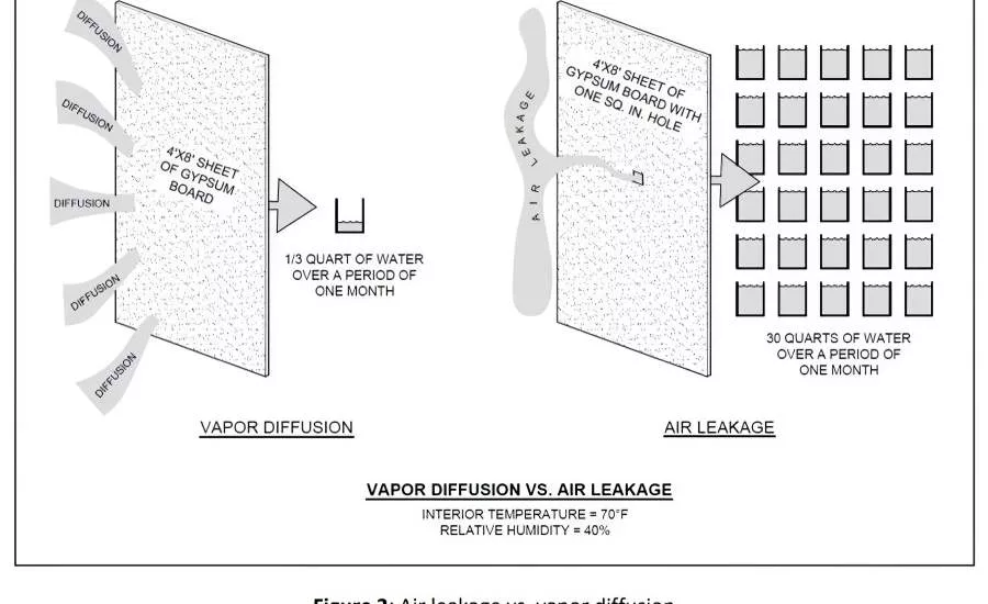
This is demonstrated by consultants Building Science Corp. through testing two 4-foot by 8-foot sheets of drywall, comparing vapor diffusion through one solid piece of gypsum wallboard to the amount of water penetrating the wall cavity when the other piece of gypsum wallboard has a 1-inch square hole cut in it.8
The conditions were:9
Position: Exterior Within Cavity Interior
Temp: 80°F 100°F 75°F
Relative Humidity: 75% 100% 60%
Vapor Pressure: 2.49 kPa 6.45 kPa 1.82 kPa
When the two drywall panels were subjected to the same conditions in the experiment, 10 pints of water was collected by diffusion through the painted gypsum wallboard (approximately 5 perms), whereas 14 pints of water was collected through the 1-inch square hole in the panel. In more simple terms, in the experiment described above, air leakage carried almost 10 times more water vapor through the drywall than vapor diffusion does. This experiment demonstrates why preventing air leakage may be a higher priority in planning for moisture management than vapor diffusion.
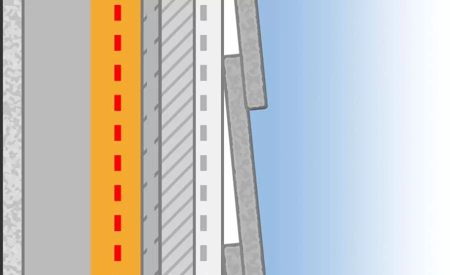
It is critical to remember that no matter how masterful the installation, the WRB and sheathing will never be flawlessly sealed. There will always be openings present where water can penetrate over time. Furthermore, each component of the wall assembly, such as insulation, will make its own contribution to the wall assembly’s total level of permeability. Use of continuous insulation can provide moisture vapor control and can function as a water-resistive barrier and air barrier.
IBC and IRC Building Codes allow for more permeable vapor retarders to be used in climate zones 5, 6, 7 and 8 when the proper amount of plastic foam continuous insulation is used on the outside of the studs.10 Specific R-values are provided in the codes based on climate zone. The amount of continuous insulation used impacts the heat transfer rate of the assembly.
Since temperature of wall assembly components determines where condensation may occur in the assembly, maintaining an assembly temperature above the dew point temperature can restrict condensation.11 Every part of the wall structure must be considered when judging the necessary perm level of the installation’s WRB.
Understanding the various factors that affect the transfer of water and air through a building’s envelope assembly helps to determine the best low or high-perm vapor retarders to use in your design to best defend against the elements, depending on the conditions that exist.
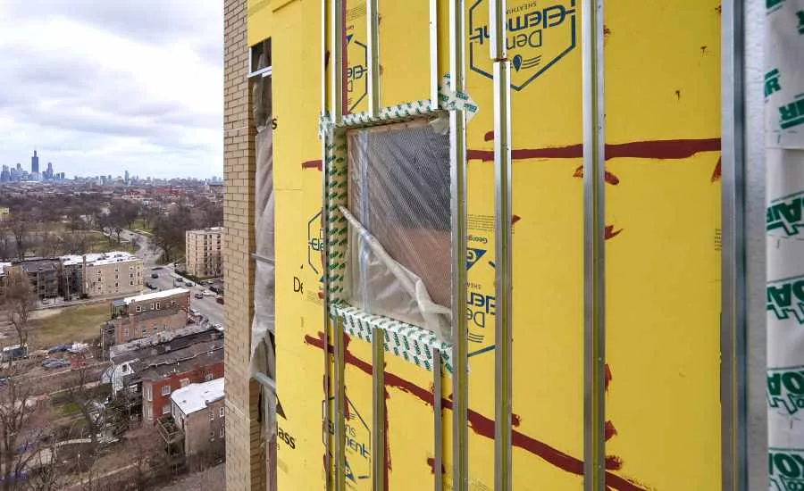
Modern Innovations in Water-Resistive Barriers
Though it is the only type of WRB called for by the code, the traditional asphalt felt papers of yesteryear no longer have widespread usage as WRBs. They have since been replaced by mechanically attached sheet products, fluid-applied membranes, self-adhered membranes, and integrated sheathing materials that have gained code approval through product/system evaluations.
Each of these material types has a wide range of function and permeability. In general, if a WRB material holds a product evaluation report, it has been tested to a specific WRB criteria verifying that the material will keep water outside the sheathing and drain the rain regardless of the permeability and its function as an air barrier or vapor retarder.
Many WRBs also have to meet compliance requirements as air barriers. These solutions have evolved over the past decades in response to demand for greater performance, durability, energy efficiency and ease of installation.12 Integrated systems have become particularly popular in recent years for their ability to save time, lower costs and produce more reliable results. Conclusion: vapor diffusion is far less of a concern than water penetration via air leaks through openings.
In Conclusion
Conventional practices reflect the belief that code only permits the use of impermeable WRBs in cold climate zones. As has been demonstrated in this white paper, that belief is untrue. Both high- and low-perm WRBs may fulfill code requirements when considered in the context of other materials within the wall assembly. Understanding code requirements and the dynamics of vapor drive are essential to designing an optimal wall assembly.
Resources
1 IMP Selection Guide.pdf
2 https://www.constructioncanada.net/condensation-on-curtain-wallsurfaces-an-investigation/
3 https://www.designingbuildings.co.uk/wiki/Cladding_for_buildings
4 https://www.designingbuildings.co.uk/wiki/Rainscreen
5 https://www.buildingscience.com/documents/information-sheets/reservoir-claddings
6 2018 International Building Code. Chapter 14. International Code Council. https://codes.iccsafe.org/content/IBC2018/chapter-14-exterior-walls
7 Cladding Attachments Put to the Test: Testing for Leakage Under Extreme Water and Wind. DensElement Barrier System Whitepaper. Georgia Pacific. https://denselement.com/blog/article.aspx?article=Technical-White-Paper-Cladding-Attachments-Put-To The-Test
8 Kohta Ueno. Moisture Safe? The Writing’s on the Wall. Building Science Corporation. https://buildingscience.com/sites/default/files/2017-03-08_nesea_be17_ueno_for_pdf.pdf
9 Moisture Safe? The Writings on the Wall https://buildingscience.com/sites/default/files/2017-03-08_nesea_be17_ueno_for_pdf.pdf
10 Designing with Continuous Insulation for Thermal and Moisture Management https://www.bdcuniversity.com/continuous-insulation-framedexterior-walls
11 Designing with Continuous Insulation for Thermal and Moisture Management https://www.bdcuniversity.com/continuous-insulation-framedexterior-walls
12 Peter J. Arsenault. The Evolution of Water-Resistive and Air Barriers in Commercial Building Envelope Construction. Continuing Education Center: Architecture + Construction. https://continuingeducation.bnpmedia.com/courses/georgiapacificgypsum/the-evolution-of-water-resistive andair-barriers-in-commercial-building-envelope-construction/
13 2018 International Energy Conservation Code. Chapter 4. International Code Council. https://codes.iccsafe.org/content/iecc2018/chapter-4-ce-commercialenergy-efficiency
14 BSD-163: Controlling Cold-Weather Condensation Using Insulation https://www.buildingscience.com/documents/digests/bsd-controllingcold-weather-condensation-using-insulation
15 2012 IECC - International Energy Conservation Code https://codes.iccsafe.org/content/IECC2012/chapter-3-ce-generalrequirements
*For purposes of this white paper, code refers to the IBC and IRC uniform code. Please consult local code for deviations. This paper is intended solely for general information and guidance. Ultimately, the design and detailing of any project, assembly or system is the responsibility of a professional, and all projects must comply with applicable building codes and standards. GP Gypsum disclaims any responsibility or liability for the architecture, design, engineering or workmanship of any project, assembly or system.
Looking for a reprint of this article?
From high-res PDFs to custom plaques, order your copy today!

.webp?height=740&t=1767036885&width=auto "Header - BE 1170x658 (002).png")

.webp?height=740&t=1755781744&width=auto "KEE(2).png")