Cyclical Testing of Flat Lock Copper Seams
The use of flat seam copper roofing in the United States dates back to the copper roofing manufactured by Paul Revere and installed on the Massachusetts State House in 1802. Since then, flat seam copper has been widely used in low-sloped roofing applications as it is a reliable, durable roofing material. History shows that flat seam copper roofing can provide a service life of 100 years, which the original Massachusetts State House roof achieved (Photo 1). However, flat seam copper roofing is expensive and is only as reliable as the quality of the seams between panels.
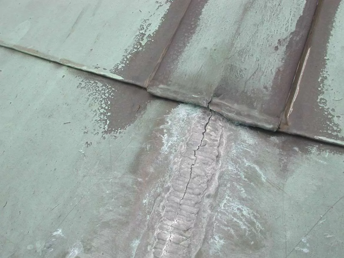
If the panels are improperly designed and installed, the service life of the roof can significantly be reduced (Photo 2). A common failure is cracking of the flat lock soldered copper seams and subsequent water leakage through the open seams (Photo 3). Although certain “best practice” guidelines by various sources have existed for years1, 2, 3, 4, the guidelines are based on practical experience instead of testing, and currently there is no industry consensus on what constitutes “acceptable” practice for constructing flat lock soldered copper seams based on in-service performance. In service, these joints are subjected to snow and wind loads, but the most demanding loads are the cyclical thermal stresses incurred during temperature swings.
This paper discusses the thermal analysis and cyclical testing that we performed under contract by the International Training Institute (ITI)5 on various qualities of 1/2-inch wide fully soldered flat copper seams to identify the minimum workmanship requirements for meeting expected in-service loads without failure over a 75-year period. This paper assumes the reader understands basics about fully soldered flat seam copper roofing. For additional information, refer to Floyd and Patel, 20166 for details on fully soldered copper roofs.

Photo 1 – Existing 90-year-old flat seam copper roofs still in service.
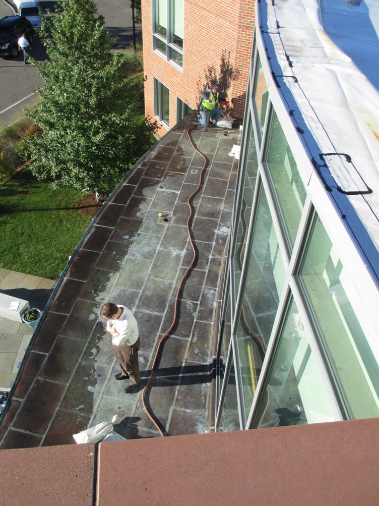

Photo 2 – Failed flat seam copper roof less than 5 years old being replaced due to failed seams.
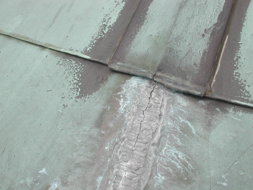
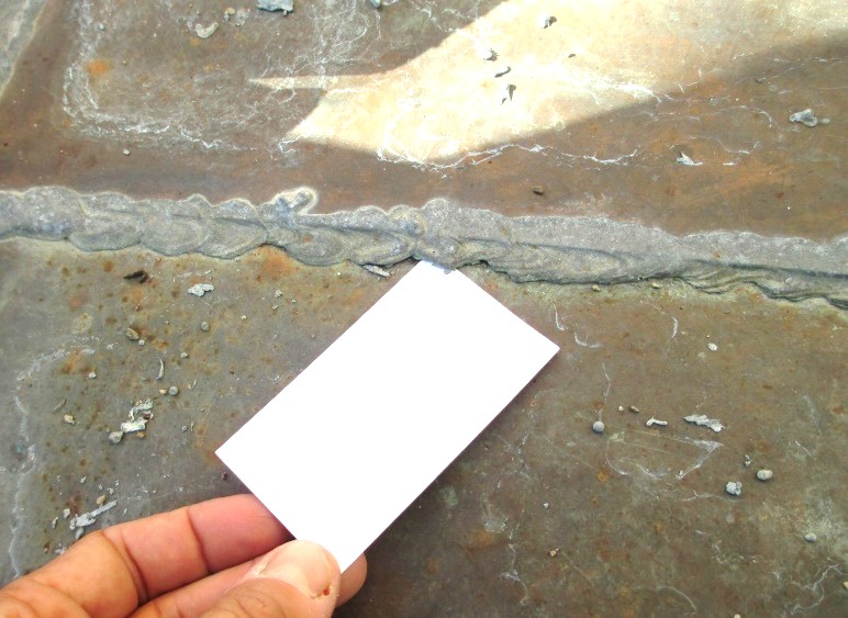
Photo 3 – Common flat seam copper roof joint failures: crack within solder joint (top), crack on edge of solder joint (bottom).
ANALYSIS
Thermal Analysis
Prior to testing, we calculated the expected loading on copper roof seams due to thermal expansion and contraction. We modelled a standard flat seam copper roof assembly (plywood sheathing, self-adhered underlayment membrane, and copper panels with 1/2-inch wide soldered flat seams as required by SMACNA standards; Figure 1) in WUFI7, a thermal and moisture modeling program which uses actual weather data from various locations (temperature, solar gain, rain, etc.), and tracks temperature and moisture data for each layer within an assembly. We used this model to obtain a profile of the roof surface temperatures for a “typical” yearly cycle based on WUFI data.
The output information from WUFI provides the amplitude of temperature swings through the system throughout a typical year at the following locations modelled: Boston; Boulder; Miami; Phoenix; and San Diego. We modeled each location using new copper and aged copper (brown color) and found that the resulting temperatures were higher for aged copper temperatures in all cases; therefore, we used aged copper for all of our models. As the copper roofing is typically attached to a plywood substrate, thermal stresses in the copper panel seams are primarily due to differential movement between the copper and the substrate. We reviewed the difference in temperature between the copper and plywood over time, shown in Figure 2 for Boulder, Co., below. We used this parameter to calculate the thermal loads within the panels.
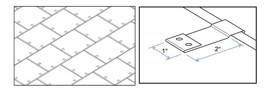
Figure 1 – Modeled roof assembly and typical flat seam construction. Copper panels are 18 in. x 24 in.
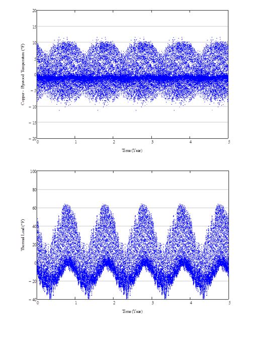
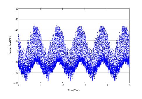
Figure 2 – Temperature differentials, Boulder
DT = Copper – Plywood Temperature (top),
Thermal Load for Installation @ 70°F (middle),
Thermal Load for Installation @ 100°F (bottom).
Stress Analysis
Using the cyclical temperature data from WUFI, we evaluated the resultant stresses at copper roof seams using a finite element analysis (FEA) model of the thermal cycling of a typical flat seam copper panel assembly. The FEA model determined the forces generated within the soldered seams due to thermal cycling, accounting for deformation of panels (i.e., buckling) that helps reduce thermal stresses. Figure 3 shows a typical FEA output. We then computed stress range cycle counts from the seam stress time history. The result was a summary of cycles within the soldered seams, away from corners and cleats, for each of the five locations studied. The summary table provides useful information regarding the annual cyclical load demand on the soldered flat seams in a panel assembly in various climates (Table 1). Based on this parametric analysis, the Boulder, Colorado, location had the highest number of cycles at various stresses (Figure 4).

Figure 3 – Contour of out-of-plane displacements in copper panels, measured in inches

Table 1 – Number of Annual Thermal Cycles (70°F installation temperature)

Figure 4 – Annual thermal cycles corresponding to 1 year of life in Boulder, CO
(70°F installation temperature)
LABORATORY TESTING
Creating and Evaluating Samples
The International Training Institute (ITI) provided soldered copper flat lock seam samples that represent varying levels of workmanship. To provide a range of conditions, the samples were prepared using five different methods by varying amounts of pre-tinning, extent of soldering through the joint, soldering speed, and amount of solder used. ITI prepared 5 groups of samples using standard practices intended to result in the highest quality solder joints. In each subsequent group of samples, the preparation method was altered to result in variable-quality solder joints. Preparation methods for each group consisted of the follow:
- Group 1 – Pre-tinning front and backside. The specimens in Group 1 were prepared using standard practices intended to result in the highest quality of solder joints.
- Group 2 – No pre-tinning. The specimens in Group 2 were prepared using the same methods used to prepare Group 1; however, the copper was not pre-tinned prior to forming the copper hook strips.
- Group 3 – No pre-tinning, solder applied to seams at a slightly faster travel pace using approximately 20 to 25 percent less solder than previous groups. The intent was to provide seams that were fully sweated through Leg 1 only.
- Group 4 – Pre-tinning of one side. The specimens in Group 4 were intended to be partially soldered into Leg 3 of the seam.
- Group 5 – Pre-tinning of one side, solder applied to seams at a slightly faster travel pace using approximately 20 to 25 percent less solder. The intent was to provide seams that were fully sweated into Leg 2 only.
We received all samples, evaluated, and recorded the following parameters (Figure 5):
- Extent of dressing down (how “flat” are the seams vertically)
- Gaps in joints (how engaged are the copper hooks horizontally)
- Voids in solder (how uniform is the solder between the copper hooks)
- Solder sweating extent (how does far the solder extend into each leg of the joint)
- Edge seam solder geometry (how much solder is installed along the edge seam)
We evaluated each specimen based on the above-listed parameters prior to and after testing was completed. We recorded measurements for each parameter on both sides of every copper specimen.

Figure 5 – Five parameters for evaluating flat lock seam solder joints
Testing Results
We performed the testing by inserting the flat seam solder samples into an Instron hydraulic universal tester and applying cyclic tension and compression loads equivalent to the annual thermal cycles corresponding to one year of service life in Boulder (Figure 4) repeatedly until either the flat seam copper samples failed or we reached the equivalent of 75 “years” of service life. At failure, we recorded the number of annual cycles to determine the effective service life of that sample. We then inspected all samples to correlate the failure mode and effective service life with the parameters noted above.
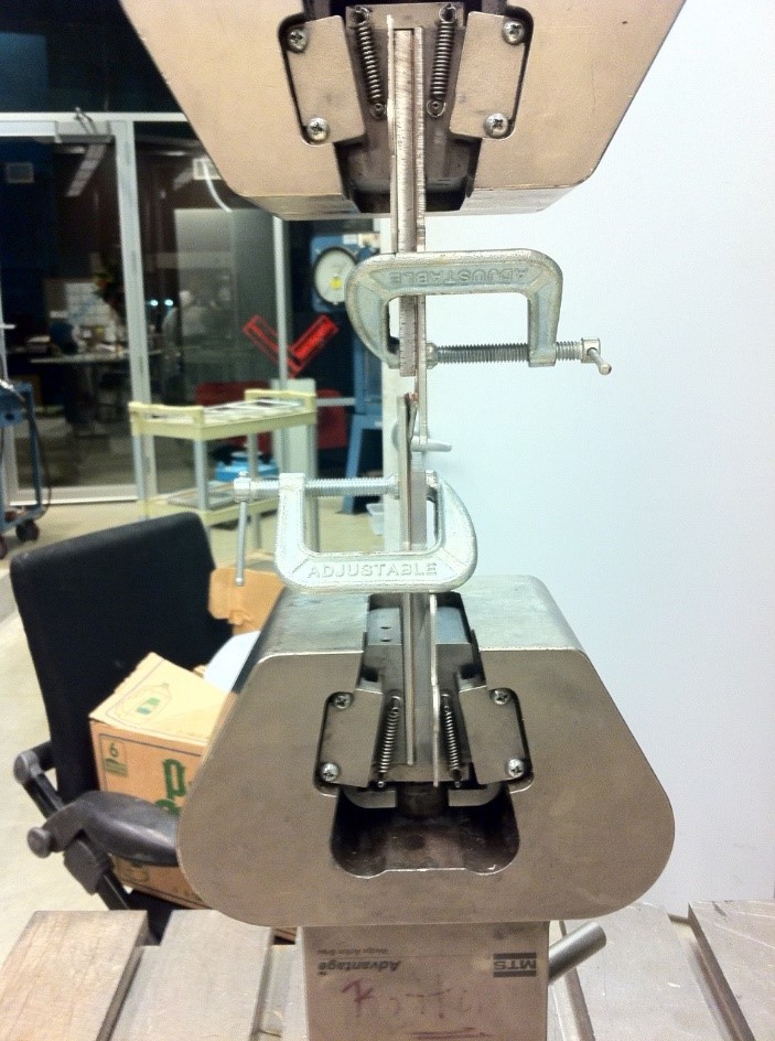
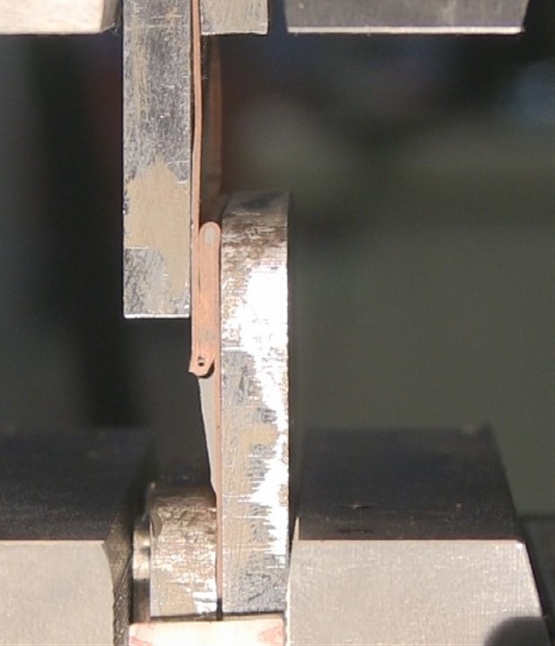
Photo 4 – Soldered seam sample in Instron tester.
Failure Modes
We observed four different failure models throughout testing (Figure 6):
- Failure Mode 1 – Copper Fracture in Leg 3 (Photo 5, top left) – Copper fracture occurs in Leg 3 of the specimen adjacent to the top bend in the hook.
- Failure Mode 2 – Copper Fracture in Legs 2 and 3 (Photo 5, top right) – Copper fracture occurs in Legs 2 and 3 adjacent to the bend in the hook. Each fracture is located at the transition between the bend and the straight legs of the hook. In samples with edge solder, the copper bend is pulled away from the edge seam solder.
- Failure Mode 3 – Edge Seam Solder Failure (Photo 4, right and Photo 5, bottom left) – The failure occurs in the edge seam solder at the copper bend during a tension cycle. The copper bend is pulled from the edge seam solder and the bond fails.
- Failure Mode 4 – Buckling (Photo 5, bottom right) – Buckling failures occur in the straight legs of the copper hook strip during a compression cycle. The offset of the sheets causes eccentricity at the seam; therefore, the principal axes rotate depending on the sample geometry. The principal axes are not oriented in the same direction as the applied loads.

Figure 6 – Four Failure Mode Locations
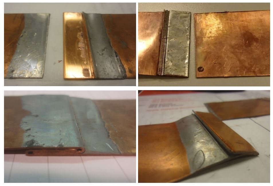
Photo 5 – Failure Modes:
Top Left – Failure Mode 1 – Copper Fracture in Leg 3
Top Right – Failure Mode 2 – Copper Fracture in Legs 2 and 3
Bottom Left – Failure Mode 3 – Edge Seam Solder Failure
Bottom Right – Failure Mode 4 – Buckling
Testing Summary
Based on our analysis and cyclical testing, we summarize the following for each group of samples:
Group 1
- Fabrication Process: Pre-tinning front and backside. The specimens in Group 1 were prepared using standard practices intended to result in the highest quality of solder joints.
- Average Service Life: 75 years without failure. All 10 specimens achieved the 75 year in-service life benchmark.
- Pre-Test Measurements: During pre-test measurements, we observed that every specimen was sweated into Leg 3 of the seam. Almost all specimens had a moderate to high amount of edge seam solder, which adds stiffness to the seams.
- Failure Mode: Only one sample failed at 75 years with a fracture in Leg 3 (Failure Mode 1). All other samples exceeded the 75 year benchmark without failure.
- Correlation: A fully sweated seam is able to resist the twisting and rotating caused by the eccentric applied loads and asymmetrical geometry of the seam.
Group 2
- Fabrication Process: No pre-tinning. The specimens in Group 2 were prepared using the same methods used to prepare Group 1; however, the copper was not pre-tinned prior to forming the copper hook strips.
- Average Service Life: 59 years. Results ranged from a minimum of 19 years to a maximum of 75 years, with 5 of the 11 specimens reaching the 75 year benchmark.
- Pre-Test Measurements: During pre-test measurements, we observed that six of the eleven specimens were sweated through the first leg only, while the rest of the specimens were partially sweated into the second leg of the seam. All the specimens exhibited voids in the solder and had solder along the edge seam.
- Failure Mode: Two prevalent failure modes. The specimens either failed due to a fracture in the copper at Leg 3 in the seam (Failure Mode 2) or a failure in the edge seam solder (Failure Mode 3).
- Correlation: Specimens with partial sweating into Leg 2 typically failed due to a failure in the edge seam solder and completed close to 75 cycles. Specimens with no solder in Leg 2 typically failed due to a copper fracture in Leg 3 and generally completed fewer annual thermal cycles than those with sweating into Leg 2.
Group 3
- Fabrication Process: No pre-tinning, solder applied to seams at a slightly faster travel pace using approximately 20 to 25% less solder. The intent was to provide seams that were fully sweated through Leg 1 only.
- Average Service Life: 37 years. Results ranged from a minimum of 7 years to a maximum of 75 years, with only 1 of the 10 specimens reaching the 75 year benchmark.
- Pre-Test Measurements: During pre-test measurements, we observed that some of the samples were fully sweated through the first leg, while some of the samples were partially sweated into the second leg of the seam. All the samples exhibited voids in the solder and a large amount of solder along the edge seam.
- Failure Mode: The specimens failed due to a combination of a fracture in the edge seam solder in the seam (Failure Mode 3) or buckling of the copper legs (Failure Mode 4).
- Correlation: We reviewed the number of annual thermal cycles completed and the joint evaluation parameters and did not observe a correlation. Specimens with similar joint evaluation parameters performed differently. The large degree of variation within the specimen group suggests that the edge seam solder may provide some stiffness to the seams. However, the results do not directly correlate to the amount of edge seam solder present.
Group 4
- Fabrication Process: Pre-tinning of one side. The specimens in Group 4 were intended to be partially soldered into Leg 3 of the seam.
- Average Service Life: 63 years. Results ranged from a minimum of 14 years to a maximum of 75 years, with 13 of the 17 specimens reaching the 75 year benchmark.
- Pre-Test Measurements: During pre-test measurements, we observed that the majority of the specimens were soldered into Leg 3 to varying degrees. In four of the samples, the solder did not extend into Leg 3. All the samples exhibited minor voids in the solder and were dressed to different extents. The edge seam solder was minimal.
- Failure Mode: All four specimens without solder in Leg 3 failed prematurely in the copper edge seam (Fracture Mode 3). All other samples exceeded the 75 year benchmark without failure.
- Correlation: We observed that every specimen that fully or partially sweated into Leg 3 of the seam achieved the 75 years in-service life benchmark. The extent of the solder into Leg 3 did not appear to affect the results as specimens with only 10 to 15 percent of Leg 3 sweated did not fail. All four specimens without solder in Leg 3 failed prematurely.
Group 5
- Fabrication Process: Pre-tinning of one side, solder applied to seams at a slightly faster travel pace using approximately 20 to 25% less solder. The intent was to provide seams that were fully sweated into Leg 2 only.
- Average Service Life: 10 years. Results ranged from a minimum of 5 years to a maximum of 17 years, with 11 of the 23 specimens failing before 10 years.
- Pre-Test Measurements: During pre-test measurements, we observed that twelve of the specimens were fully sweated in Legs 1 and 2. Six of the specimens were sweated in Leg 2, but only partially sweated in Leg 3.
- Failure Mode: All samples failed prematurely due to copper fracture on Legs 2 and/or 3.
- Correlation: The sample group performed poorly due to a lack of stiffness within the soldered seam. Without enough solder to stiffen the seam and allow it to transfer loads without stress concentrations, the sample is subjected to differential movement and fractures in the copper legs. The results of this sample group demonstrate the inherent weakness of soldered seams that are only sweated through one or two legs.
Conclusions
Our testing shows the most important factor in determining the quality of a copper soldered seam is the extent of the solder sweated through the seam. A copper seam with solder extending into the third leg can be expected to surpass a 75 year service life. In practice, full sweating is more difficult on wider flat seam joints and those that are not properly fit together in the field; our testing demonstrates that 1/2-inch wide joints are adequate if properly sweated (Photo 6).
Further, the test data showed the following regarding the effects of various physical conditions to the service life of soldered joints:
- Sweating into Second and Third Legs: The sweating extent of the solder within the seam determines the quality and in-service life of soldered seams. A seam that is sweated into the third leg regardless of extent can be expected to achieve a 75 year in‑service life. A seam that is partially sweated and is not sweated into the third leg is likely to fail prematurely.
- Voids in Solder: Voids in the solder at seam bends had little to no effect on service life.
- Dressing Extent/Presence of Voids and Joint Gaps: To a certain degree within the variances of the samples we tested, the dressing extent, presence of voids, and presence of joint gaps have minimal effect on the performance of the seam if the solder is sweated into the third leg.
- Edge Seam Solder: A build-up of edge seam solder can extend the in-service life of a seam. The edge solder provides stiffness and may extend the life of a poorly installed, partially sweated seam; however, service life results were extremely variable (minimum 7 years to maximum 75 years). Adding large amounts of edge seam solder is not a reliable method and should not be relied upon (i.e., the focus should be to achieve fully sweated joints).

Photo 6 – Ideal flat lock joint that is dressed, fully sweated, no solder voids, and minimal edge solder
Recommendations
When it comes to designing, specifying, and evaluating fully soldered seams, we recommend that design professionals focus on the following quality procedures during design and construction specifically focused on evaluating seaming. Many other design and construction considerations exist related to proper flat seam metal roofing construction, such as proper thermal movement joints, attachment, underlayment, slope and drainage, corrosion and staining considerations, etc.; these items are beyond the scope of this article.
- Design Professionals: Properly detail and specify the flat seam joinery based on industry standards, including joint and panel sizes and panel layout. Specify quality control procedures as outlined below. Engage design professionals experienced in designing flat seam roofing systems.
- Contractor Experience: Use installers experienced in sheet metal construction and soldering in particular, with demonstrated successful past project experience. Provide proper training for all installers, such as through the International Training Institute.
- Contractor Soldering Tests: Require that each installer of soldered work perform soldering tests prior to the start of work and periodically during construction for approval by the design professional. Only approved installers should be solder sheet metal work on larger projects.
- Perform destruction evaluation of the soldering samples and evaluate the joint based on industry standard requirements (e.g., SMACNA1). Evaluate all soldered test seams by cutting the seams into 2-inch wide strips and inspecting each side for dressing extent, voids in solder, joint gaps, and sweating extent. Reject all samples where the joints are not sweated into the third leg at least 10 percent.
- Mockups: Require that the contractor construct mockups prior to the start of work.
- Inspectors: Engage a part-time or full-time roofing inspector during fabrication and installation.
References
- Sheet Metal and Air Conditioning Contractors’ National Association (SMACNA) (2012). Architectural Sheet Metal Manual.
- Revere Copper Products, Inc. (2005). (8th ed.). Copper and Common Sense. Revere Copper Products, Inc.
- Copper Development Association (Year). Copper in Architecture – Design Handbook. Copper Development Association Inc.
- National Roofing Contractors Association (NRCA) (2020). The NRCA Roofing Manual: Metal Panel and Roofing Systems. NRCA.
- SMACNA (2018). Technical Resources Bulletin No. #01-18 – Flat Lock Seam Soldered Copper Joints Study.
- Floyd, N.T., and Patel, A.K. (2016). Fully Soldered Metal Roofing – More Complicated Than You Think. 2016 Symposium on Building Envelope Technology, Houston, TX.
- WUFI Software. http://www.wufi.de/ (accessed 2011).
Looking for a reprint of this article?
From high-res PDFs to custom plaques, order your copy today!


.webp?height=740&t=1767036885&width=auto "Header - BE 1170x658 (002).png")

.webp?height=740&t=1755781744&width=auto "KEE(2).png")