Brick Veneer Failures at Relief Angles
The Importance of the Building Enclosure Process
This article presents two examples of deficient installation of a simple architectural detail, the brick veneer relief angle, and discusses how a well conducted Building Enclosure Commissioning (BECx) process can help prevent such failures.
As a provider of BECx services I sometimes perceive that the importance of our contribution to the design process is not fully appreciated. It is not rare for design teams to completely disregard the recommendations that we offer during our third-party design reviews. However, in the course of visiting jobsites and observing how building enclosure systems actually get put together I often get to see first-hand what can happen when poorly developed installation details make their way to the hands of well-meaning contractors.
A quick refresher on relief angles: as most professionals know, relief angles are required to support the weight of brick veneer at certain intervals. Per code, with wood and steel stud wall systems, relief angles must be provided at each floor when the wall height exceeds 30 feet (per the prescriptive design method of TMS 402/602 Building Code Requirements and Specification for Masonry Structures).
While the structural aspect of relief angles is usually well understood, the water management issues associated with their introduction in the wall cavity are not always fully mastered. The introduction of relief angles in the wall cavity requires providing thru-wall flashings at each angle, as the angle typically blocks the drainage path within the wall cavity. Proper detailing and installation of this detail is critical, because trapped water can result in corrosion of the shelf angle or moisture intrusion. The Brick Industry Association of America (BIA), among others, provides clear guidelines on how such thru-wall flashings should be detailed for successful performance (refer to the BIA technical note TN 18A).
Additionally, it is critical to ensure that the detail allows for expansion of the brick veneer. Clay bricks expand irreversibly over time upon exposure to moisture. This expansion can be significant. BIA technical note TN 18 recommends assuming a design coefficient of 5x10⁻⁴ in./in for moisture expansion. To accommodate for moisture expansion and other differential movement, a minimum gap of 1/4 inches should be left under the shelf angle. If no accommodation is made for expansion, the bricks below the angle may eventually push up against the angle, and the resulting compressive forces can cause the bricks to crack.
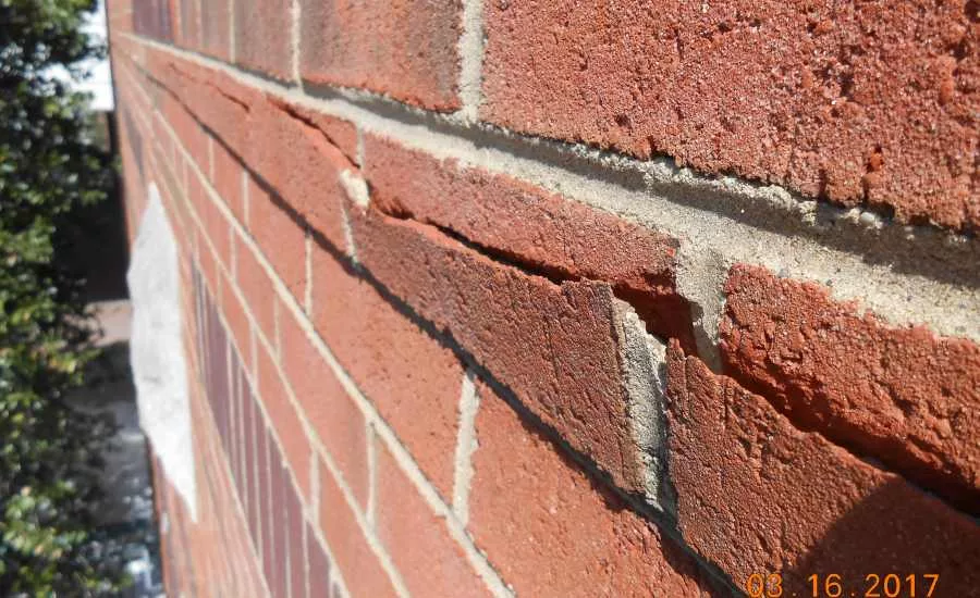
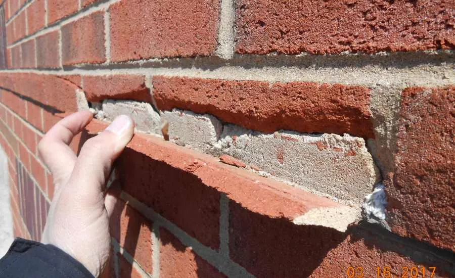
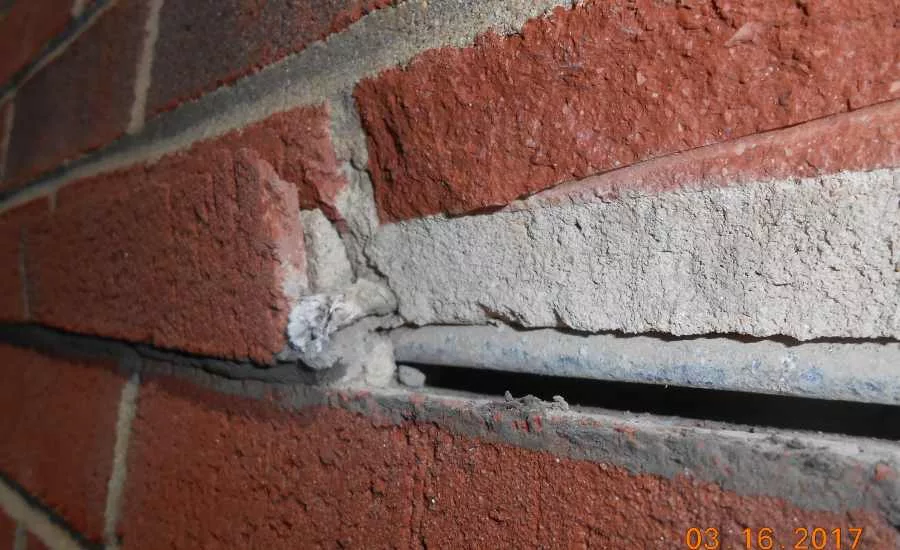
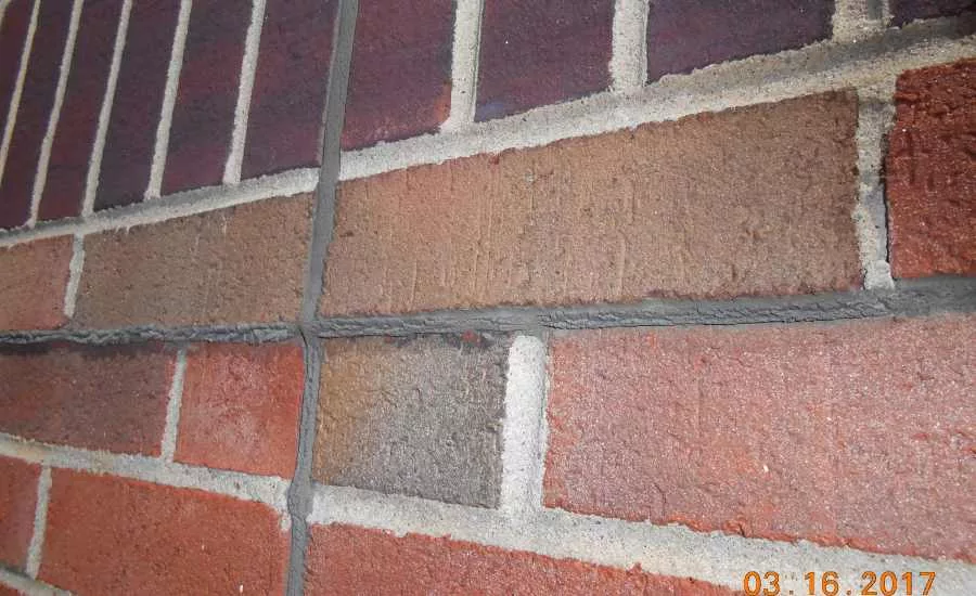
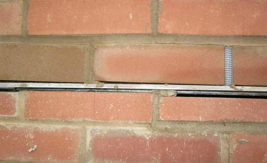
Figures 1-4 were observed while performing a condition assessment of a four-story steel framed building constructed around 1996. Multiple bricks under one of the shelf angles were spalled and barely clung to the wall thanks to the adhesion of the sealant joint. This created a major inconvenience for the owner, as in addition to allowing excessive amounts of water to enter the wall cavity, the impending fall of the brick fragments created a significant safety hazard to the unsuspecting pedestrians below.
As mentioned above, relief angles are commonly used, and many resources offer clear guidelines on how they should be detailed and installed. So what exactly went wrong here? After close examination we identified multiple factors in the installation contributing to this failure:
- No metal drip edge flashing was provided.
- The sealant joint was adhered to the bricks above the angle, trapping water at the toe of the angle.
- Minimal drainage was provided via cotton wicks in lieu of the much more efficient open head joints that are typically used.
- Lipped bricks above the angle were improperly installed. The lower part of the lip was lower than the underside of the shelf angle. When the bricks below expanded, they came into contact with the underside of the lipped bricks and caused them to crack. The underside of lipped bricks should align with the underside of the shelf angle.
- Field-fabricated lipped bricks were used. This resulted in deep, irregular saw cuts that weakened the bricks.
Assessing Responsibility
Part of the responsibility for this failure falls on the installer. The cracking may not have occurred if the lipped bricks had been installed properly above the angle, leaving a sufficient gap between the bricks below. This kind of deficiency could have been caught and corrected during installation if an experienced consultant had performed site visits to review the work as part of a quality control program.
However, close examination of the as-built architectural drawings pointed fairly strongly in the direction of the architect as the main culprit in this case. We were surprised to realize that the architectural drawings contained absolutely no detail for the relief angles. Apparently, the design team relied on the mason’s expertise to ensure a proper installation. Unfortunately, not all masons have enough initiative and knowledge to come up with proper detailing in the field.
It is worth noting as well that laborers can only install the materials that are provided to them. Since the bidding documents did not specify how the relief angle should be installed, the contractor did not make allowances to procure a metal drip edge flashing. Had this flashing been provided to the installers it is likely that they would have installed the sealant joint correctly, between the lower brick and the flashing instead of between the two brick courses.
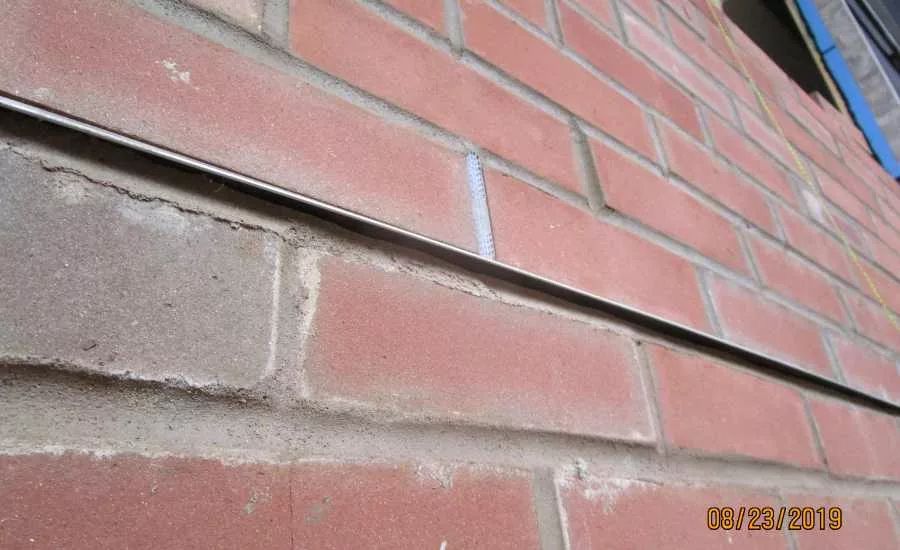
The next example provides another case of an incorrectly installed relief angle. We reported this deficiency while performing site visits on a project where we were providing full commissioning services. Again, as can be seen on Figures 5 and 6, this installation was deficient in multiple ways:
- Some of the bricks are installed tight against the underside of the shelf angle (no allowance for expansion).
- Mortar is used in lieu of sealant under the shelf angle (mortar is likely to crack and fall off following brick expansion).
- The bricks at the last course under the relief angle are cut to fit under the angle. Competent masons normally size their mortar joints to ensure that the last course fits under the angle.
- Lipped bricks, which were required per the details, are not provided.
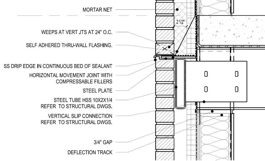
This is a recent, four-story institutional building constructed per standard industry practices. How can such a simple detail have turned out so poorly executed? In this case, the architectural drawings did contain a relief angle detail. Unfortunately, as is sometimes the case in some projects, the installation details were mostly conceptual in nature and the relief angle was ambiguous and insufficiently detailed (refer to Figure 1):
- The scale is too large, and finer details are hard to see, even after zooming in on the screen. And anyway, installers don’t have screens in the field, they rely on paper.
- A gap is correctly shown under the shelf angle, but no dimension is specified. In the installer’s mind when something doesn’t have a dimension then it doesn’t exist.
- No sealant joint is shown under the angle. That pretty much guaranteed that the sub-contractor would not provide sealant to his installers, as he bid the job assuming no sealant joint was required. When the installer saw an unsightly irregular void under the angle, he naturally filled it with the mortar he had at hand, completely oblivious to the fact that the mortar would likely crack and fall off once the brick expands, or even cause the brick itself to crack.
Honoring the Process
Similar to the previous example, poor workmanship and lack of experience on the mason’s part was largely to blame. This was not the only issue noted with the masonry on this project, suggesting that this particular contractor may not have been the most experienced. As commissioning agents, we have no control over the skills level of the sub-contractors, and all we can do is to report issues that can be objectively identified as deficiencies based on accepted guidelines. In this particular case we were able to refer to BIA technical note TN 18A to objectively demonstrate that a gap was required under the relief angle, and the masons agreed to install sealant instead of mortar. However, it was much harder to argue that the last brick course should not have been cut, as this is more of an unwritten convention.
Another factor that contributed to this failure was the lack of pre-construction coordination. No mockups were provided, and no pre-construction meetings were held. As part of the commissioning process, we always encourage holding pre-construction meetings. These meetings should be held with the applicable contractors prior to the start of installation of each major system: weather barrier, masonry, wall cladding, etc. These meetings are essential for coordinating the installation details between adjacent systems, which typically get installed by different trades. It is not rare that the shop drawings for two adjacent systems show conflicting details. In this particular project, a pre-construction meeting would have allowed us to discuss the shelf angle detail and make sure the masons understood the need for leaving a gap under the angle, for example.
Mockups are another important part of pre-construction coordination that we try to encourage as part of building enclosure commissioning. Mockups incorporating every building enclosure component should ideally be fully detailed on the construction documents. If a wall mockup had been provided on this particular project, it would have been immediately obvious that the details did not show a sealant joint.
Some deficiencies can also be caught at the submittal review stage. Review of shop drawings is critical for systems that include transitions to adjacent systems, such as for roofs, insulated metal panels, or curtain walls. In this case, if a complete submittal had been provided for the brick veneer product data it might have been possible to identify that the mason had not intended to use lipped bricks.
In summary, a well conducted building enclosure process can help prevent the kinds of unfortunate failures we discussed by providing the following:
- Meticulous third-party design review of the architectural details. The drawings should be clear, unambiguous, and include transition details to adjacent systems. This is surprisingly too often not the case, even for common details.
- Insisting on providing mockups. This should be a requirement included in the contract documents at the design stage.
- Holistic review of the submittals, particularly shop drawings.
- Participation in preconstruction meeting.
- Performing site visits to review the installation in progress.
As we have seen, while the building enclosure process can sometimes seem superfluous, our experience demonstrates that it can help prevent costly failures by identifying issues before they become irreversible, either during the design review, pre-construction, or construction phases.
Looking for a reprint of this article?
From high-res PDFs to custom plaques, order your copy today!
.webp?height=740&t=1767036885&width=auto "Header - BE 1170x658 (002).png")

.webp?height=740&t=1755781744&width=auto "KEE(2).png")