Integrating Shading Devices with the Building Envelope
In this age of green imperatives, architects designing commercial and institutional structures are usually on the lookout for ways to add incrementally to a building’s overall energy efficiency. One of the many options available to them is to add shading devices to the exterior to reduce solar heat gain (SHG) through the building envelope, while creating elements of visual interest.
Exterior shading devices are among the structural considerations available to reduce the amount of direct solar rays impinging on the outside face of vision glass and entering conditioned space. When properly dimensioned, based on the latitude of the project site and orientation of the façades, such devices on south-, east- and west-facing walls shade windows or curtain wall expanses from the high summer sun to reduce cooling loads on HVAC systems, but admit the low-angle winter sunlight to supplement heating. In some cases, horizontal shading devices can also redirect natural daylight upward, increasing its penetration into occupied spaces and allowing reduced levels of artificial lighting. Horizontal shading devices are typically useful on south elevations, while vertical shading devices are well suited for east and west elevations.
To aid the designer in addressing shading device design and application concerns, the American Architectural Manufacturers Association (AAMA) has released a new Technical Information Report that focuses on the design and attachment of shading devices: AAMA TIR-A16-19, Design of Exterior Shading Devices.
To avoid some of the technical and practical issues that can arise from improper design or application of shading devices, TIR-A16 should be used in conjunction with AAMA 514, Standard Test Method for Static Loading and Impact on Exterior Shading Devices, to aid in preparation of architectural drawings and specifications, shop drawings and structural calculations, and maintenance programs.
Shading device alignment and configuration typically are driven by sunlight analysis to maximize the natural lighting of a building, while optimizing solar gain and reducing glare. The first step is to determine the solar position, which is defined by two angles: altitude (height in degrees above the horizon line perpendicular to the wall) and azimuth (direction the wall faces). The net angle at which the sun hits the glass surface is called the incidence angle. In higher latitudes, the sun stays lower in the sky, but can rise and set north of due east and west, causing early morning and evening glare issues. In lower latitudes, solar altitude is greater, which adds appreciably to the heat load on HVAC cooling systems. There is no single configuration that is suitable for all locations in the U.S., and computer modeling can be useful to enhance shading design.
Equations are provided for calculating the depth required for a shading element or the extent of shadow cast by a shading element with a given depth. For example, to size an overhang or fin, h = [D x tan (solar altitude) / [cos (solar azimuth – window azimuth)]. For total shade, “h” should be the total height of the window and solve for “D,” the overhang depth. For partial shade, “h” should be the desired shadow height on the window.
With a given overhang, set the overhang depth (D) and find the height (h) of the shadow it will cast at the target month or hour.
Materials
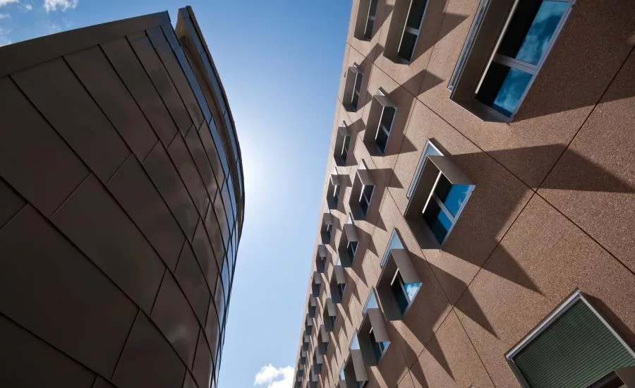
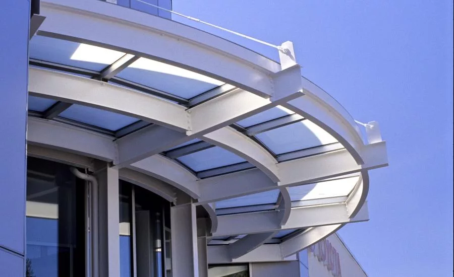
An exterior shading device is defined as a horizontal projection of more than 4 inches (100 mm) measured from the exterior glass plane. Such devices can be made from aluminum sheet, extrusions, stainless steel, glass or other solid materials. They can take the form of sun shades, glass awnings, deep snap-on covers and louvered shading devices with outriggers. They may include louver blades, cross members, nosings or a combination of these.
For unique aesthetic impact, designers sometimes select architectural glass as a shading device material, with tinted glass or silk-screened frit patterns imparting interesting visual effects in transmitted daylight. Glass in shading devices can be self-supporting or framed with aluminum members, captured or structural silicone glazed. Designers should consider employing laminated glass to help ensure that lites are retained in the event of breakage.
Of course, material selection has an impact on weight and shading performance. The architect should select the material early in the design process to properly evaluate the shading devices’ design.
In both new construction and renovation, the use and application of shading devices will have effects on elements of the “host” building’s envelope. The most significant and critical impact of these is the added loads imparted to the host system. These may include, but are not limited to the dead load of the weight of the shading device, as well as live or dynamic loads caused by wind, snow and ice.
The loads manifest as moments at anchor points and deflection of the blades, limited to the length (L) of the sun shade parallel to the building façade divided by 120 (L/120).
For example, for a louvered outrigger configuration with multiple blades, the moment (M) at the anchor point is given by: M = [(P)(L)(D2)]/2
The blade deflection is Δ = [5[(D/n)(P)]L4 ¸ 384 (E)(I), where
D = the depth of the sun shade
P = total load or combined design load (wind + snow) per unit area
n = number of blades including fascia
E = modulus of elasticity
I = weak axis moment of inertia of the blade
Again, the calculated deflection should be compared to the recommended maximum of L/120.
The equations differ for a single-blade outrigger configuration.
While there are many design considerations, key design focal points include:
- Thermal bridging (where the addition of the sun shade or its brackets could cause a thermal “short circuit” impacting the overall thermal transmittance and/or condensation resistance of the system, and which can be prevented by specifying brackets with a thermal break)
- Thermal stress on glazing (where partial shading of an expanse of glass can induce stress due to differing thermal expansion rates)
- Wind-induced vibrational resonance
- Ice and snow build-up in winter
- Effects from interfacing with building maintenance, where maintenance devices such as window washing equipment could obstruct access to the wall for cleaning or repairs, and build-up of contaminants could be promoted
- Differential thermal movement
A note about differential thermal movement: because shading devices are directly exposed to solar heat gain, as well as hot and cold weather extremes, they may experience greater thermal movement than the structures to which they are attached. Also, such as when attaching brackets to vertical expansion mullions or when sun shades span a building expansion joint, the brackets can see relatively large (> 1/4 inches [>6 mm]) horizontal movement between any two brackets.
Attachment Concerns
Shading devices are supported from window or curtain wall framing members, using specialized brackets or anchors. Some are supported by outriggers, which in turn are attached to building structural elements, or to window or curtain wall mullions. In other cases, exterior shading devices are, in essence, extensions of exterior framing or trim members, or covers. The terms “clips, brackets, arms and anchors” are all used to describe components that attach an outrigger or shading device to a mullion, other fenestration framing member or building structure.
A typical sun shade system consists of two major components: the bracket that attaches to the structure or fenestration product, and the arms or blades attached to the bracket. The blades are attached to an arm on each side to make up a "bay.” Then, each bay is fit between a pair of brackets and bolted together.
Architectural manufacturers provide outriggers and blades in a variety of shapes. Selection of the outrigger and blade shape is driven by aesthetics and shading strategy, and selection of the shape and size must be completed prior to any sunlight analysis. Because of the variety of shading devices, a custom attachment bracket may be required to correctly attach it to the fenestration system.
Note that connection points may penetrate primary seals of the host building envelope or interfere with continuous sealant lines compromising its water penetration and air infiltration resistance. If the shading device and the host system include dissimilar metals, an accepted means to separate incompatible materials should be employed.
As noted earlier, in colder climates, ice and snow will likely accumulate on shading devices, or they can be impacted by snow or ice falling from upper stories. To forestall possible damage from such situations, as well as mitigate potential damage from misused or failed maintenance equipment, the shading device should be designed to “fail safe.” This means that in the event they are damaged by impact, the shading device remains restrained by wire lanyards or harnesses, deformable brackets, or mechanical fasteners.
Renovation
While most often employed in new construction, exterior shading devices are sometimes added to existing buildings or incorporated into replacement windows or recladding, such as curtain wall or window wall. In these cases, remember that the additional load on the supporting members was not part of the original design and may overstress the supporting members or perimeter attachment, potentially causing the entire system to fail.
Existing buildings or fenestration systems and their anchors may not be sufficient to safely accept the added loads, especially those from wind, snow and/or ice accumulation on the shading devices. Before proceeding with the design of added shading devices for an existing building, the structural capacity, and condition of existing components and structures should be verified.
This inspection and analysis should include flexural deflections and stress, dead load support, lateral buckling, thermal expansion provisions, anchorage, fasteners, welds and substrates. Also, look for structural damage or deformation, water intrusion, condensation damage, corrosion or other detrimental conditions, along with any noticeable installation issues related to alignment, plumb, square and/or level. When properly applied, shading devices offer a straightforward way to improve the efficiency of the building envelope and enhance aesthetics, adding to overall value of the structure.
Copies of TIR-A16 and AAMA 514 may be obtained by visiting:
https://pubstore.aamanet.org/pubstore/ProductResults.asp?cat=0&src=A16
https://pubstore.aamanet.org/pubstore/ProductResults.asp?cat=0&src=514
Looking for a reprint of this article?
From high-res PDFs to custom plaques, order your copy today!
.webp?height=740&t=1767036885&width=auto "Header - BE 1170x658 (002).png")

.webp?height=740&t=1755781744&width=auto "KEE(2).png")