Thermal and Dew Point Transfer
How to Avoid Issues Related to Steel-Deck Fasteners
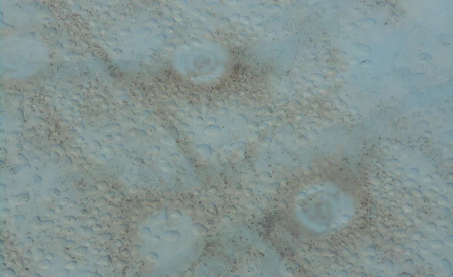
Heat loss at roof fasteners on low-slope roofs. Photos courtesy of John A. D’Annunzio.
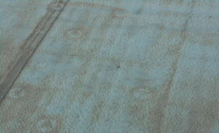
Heat loss at roof fasteners on low-slope roofs. Photos courtesy of John A. D’Annunzio.
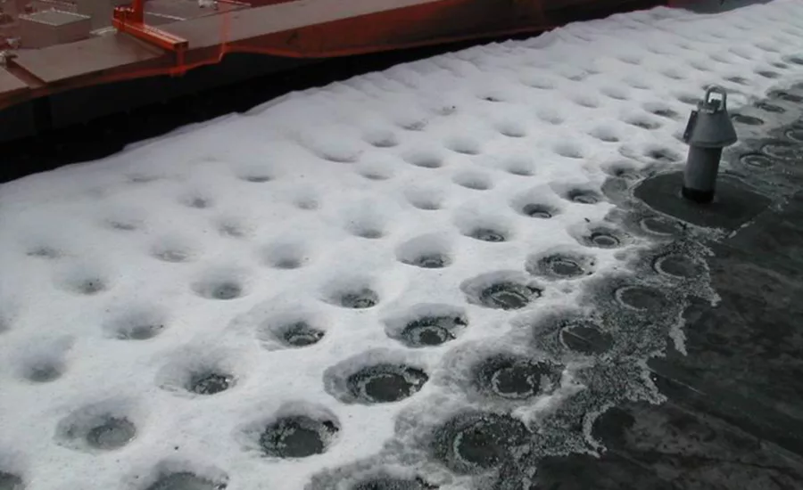
Roofs are the largest building envelope component. Due to this fact, they have the potential to provide significant energy-efficient savings. Roof systems have an impact on energy efficiency through thermal capacity, reflectivity and emissivity. The largest energy efficiency savings can be realized through the use of thermal insulation. The design requirements of thermal insulation on low-slope roof systems have changed within the last decade due to new regulations and code changes. The primary changes are related to securement to the deck, to prevent wind uplift and thermal value requirements—all for energy efficiency. Although these are separate regulations, together they have an impact on the energy efficiency of the roof system.
Securement to the Deck
Perhaps the biggest change in low-slope roof construction in the past decade has been the attachment methods and materials used for the attachment of the system components; insulation to deck, insulation to insulation, and insulation to membrane. Since the late 1990s, there has been a steady increase in the use of adhesives as primary attachment materials for insulation and membrane. These changes were predicated by the rapidly decreasing use of hot bitumen’s (asphalt and coal-tar) and advancements in adhesive technology.
Hot asphalt was the primary attachment material—insulation to deck and insulation to insulation—for over 100 years until securement methods to metal decks changed in the mid-1980s. The securement methods of insulation to metal decks changed based on requirements established by Factory Mutual in an effort to decrease wind uplift damage to roof systems in high velocity wind zones. The Factory Mutual approval requirements, which were recognized by the National Roofing Contractors Association and are now Industry Codes, stated that attachment of insulation to metal decks must be accomplished with fasteners and plates. Application of insulation to metal deck with hot asphalt is no longer acceptable. Furthermore, the fasteners and plates were to be applied in the rate and pattern established by FM or ANSI based on wind zone of the geographic location of the building. Since metal decks are the most common type of roof decks used in U.S. low-slope roof applications, these securement requirements have become a mainstay in the industry.
The attachment methods of insulation to insulation have also changed. On metal deck applications fastening through all layers of insulation is permitted. The use of low-rising foam adhesive to attach insulation to insulation is also acceptable and has become the most common attachment method in the past decade.
Thermal Value Requirements
In a roof system, thermal capacity is achieved through installation of an insulation system with high R-values. In commercial, low-slope roof systems the insulation is a rigid board that is continuously applied above the deck. High thermal value insulation can reduce heat loss in the winter months and provide energy-efficiency savings by decreasing heating costs through less energy capacity.
Roof insulation regulations have recently changed with the adaption of ANSI/ASHRAE 189 standard for the Design of High Performance Green Buildings to the International Building Code. This new regulation provides minimum requirements for high performance green buildings. The standard covers all new buildings and new systems in existing buildings except low-rise residential buildings.
This regulation now provides the requirements for roof insulation R-values for every region of the country. Prior to this regulation, there were no code requirements for minimum roof R-values. The regulation also changes the formulation of how roof R-values are determined. Prior to this regulation, roof R-values were based on the entire roof system; i.e. deck, air film, underlayment, insulation, membrane and surfacing. The ASHRAE 189 regulation defines the R-value as only the insulation system (i.e. bottom board and cover board). It also defines R-value based on the materials Long-Term Thermal Value (LTTR) as opposed to the initial R-value at manufacturing. The insulation manufacturers provide LTTR values for all of their insulation materials based on the thickness of the material.
The current ASHRAE 189 insulation requirements are as follows:
BUILDING ENVELOPE REQUIREMENTS ROOFS; INSULATION ENTIRELY ABOVE DECK
Climate Zone R-Value
1 15
2 20
3 20
4 20
5 20
6 20
7 25
8 25
Thermal Bridging of Roof Fasteners
The increased amount of insulation thickness required to meet energy codes and the increased amount of fasteners required to meet wind codes have largely positive effects on low-slope roof systems. One drawback is the thermal bridging that occurs when only a single layer of insulation is applied or when all insulation layers are fastened to the deck. Thermal bridging occurs at building points where there is heat loss between conditioned interior spaces and unconditioned exterior spaces. Thermal bridging can occur at several points throughout a building particularly at openings in the building envelope. The most common method of eliminating thermal bridging is through the application of continuous thermal insulation throughout the building envelope. Air cavities and hard to reach points can be filled with SPF insulation to eliminate air gaps that contribute to thermal bridging.
In roof systems, thermal bridging occurs when the fasteners extend from the conditioned interior space, through the insulation, to just below the unconditioned roof membrane at the exterior and the heat flows outwards through the fastener. Thermal bridging can occur when there is a slight temperature differential between interior and exterior spaces, such as when the temperature difference is sufficient enough for dew to form on the roof surface. The effects of thermal bridging are more pronounced when there is a layer of snow on the roof surface. At these times, thermal bridging is clearly illustrated because the snow melts at all of the fastener heads throughout the roof surface leaving a pattern of openings in the snow. It often appears as if a rabbit ran across the roof.
Thermal bridging can create two potential problems on a low-slope roof system:
1. There is heat loss through the roof system, which can potentially decrease energy efficiency.
2. Thermal bridging contributes to condensation, which could occur where sub-freezing outdoor temperatures are met with rising heat circulated from the warmer interior spaces. (A study conducted by SFS Intec indicates that condensation can occur at fastener point when interior temperature is 68 degrees Fahrenheit, the outside temperature is 48 degrees F and the interior relative humidity is 50 percent.)
There is no debate that thermal bridging occurs at fastener points that are exposed to exterior temperatures, however, the overall impact of thermal bridging of a roof system depends on several variables. Heat loss is determined by calculating the total of the thermal bridge area (fasteners and plates) by the total roof surface. The true amount of heat loss may fluctuate based on the type of fasteners and plates used, the thickness of the insulation and the outside air temperatures.
Proper Design to Eliminate Thermal Bridging
The effect of thermal bridging on some low-slope roof systems may be minimal. However, in today’s building environment where energy efficiency is paramount, the designer must provide all energy-efficient solutions. The most common and efficient way to eliminate thermal bridging in low-slope roof systems is by adhering a cover board insulation over the bottom layer of insulation and covering the fasteners and plates. The cover board will serve to insulate the fastener, eliminating energy loss and possible thermal bridging at fasteners and insulation joints.
This attachment method reduces the shank length of the fastener by as much as half of the total insulation thickness. The fastener is only required to penetrate through the bottom layer of the insulation. Specify the fasteners and plates required by the roof system manufacturer, as these types of materials will reduce possibility of condensation. The cover board is adhered to the bottom layer of insulation using a low-rise foam or another specially formulated adhesive required by the roof system membrane manufacturer.
The best design practice is to specify that all insulation joints (bottom and top layer) should be butted together with no gaps and all insulation joints should be staggered. Staggering the insulation joints between the two layers of insulation will block the vertical paths of upward moving water vapor that could condensate at the cold side of the membrane and contribute to the formation of membrane ridges.
In addition to eliminating thermal bridging, the installation of a cover board provides many other advantages for all types of conventional low-slope membrane systems. The primary advantage of cover board insulation is that it provides a smoother top surface for the application of the membrane. Single-layered insulation often conforms to irregularities in the substrate creating an uneven, warped surface. Studies have indicated that warping of insulation is reduced in double-layered applications because proper adhesion between insulation boards is easier to achieve than it is between the insulation and substrate. This is also true because the joints of the top layer of insulation are offset from the joints of the bottom layer to form an almost continuous plane. This is an important characteristic in adhered membrane systems because membrane adhesion is more successful over flat, stable surfaces.
Double-layered insulation is more preferable over metal decks, which account for the majority of roof substrates in the United States commercial roofing market. Applying a cover board over mechanically attached insulation offers these distinct advantages.
Another major advantage of cover boards is that they eliminate protrusions to the membrane surface from backed-out fasteners created by thermal contraction stress. This is a common source of membrane openings in single-ply membrane systems. The openings to the membrane created by backed out fasteners are sources of moisture infiltration that could enter into the roof system. The installation of cover boards prevents the need for continual membrane repair throughout the service life of the system.
Looking for a reprint of this article?
From high-res PDFs to custom plaques, order your copy today!
.webp?height=740&t=1767036885&width=auto "Header - BE 1170x658 (002).png")

.webp?height=740&t=1755781744&width=auto "KEE(2).png")

.webp?height=200&t=1760965913&width=200 "Waterproofing(2).png")