Details: Roofing
Detail courtesy of Alvaro Mejia, IRT Inc.
As is the case with all roofing systems, installation of flashings and penetrations are the most critical points of application. These areas typically account for nearly 80 percent of all reported roof leaks. These areas are particularly critical on low-slope standing seam metal roof systems because the metal serves primarily as a watershed. The water shedding capacity is functionally similar to roof shingles - it relies on a steep slope to rapidly shed the water. In contrast to waterproof roofs, which are intended to function under occasional standing water, metal roofs are not designed to be completely leak-free under long-term water immersion. Therefore, waterproofing must be provided at critical junctures, such as penetrations and flashings.
Detail courtesy of Alvaro Mejia, IRT Inc.
Proper roof design on low-slope standing seam metal systems should limit the amount of pipes, ducts and openings for rooftop-mounted equipment. Every roof penetration or opening results in cuts in the field of the metal panels. These cuts can restrict temperature expansion, expose the metal to corrosion, and lead to leaks. Eliminating these types of penetrations may not be feasible. In instances where they are required, penetrations and openings should be carefully detailed to both allow for panel movement and eliminate moisture intrusion. In architectural panels with underlayment, it is critical that all penetrations through the felt are detailed as extensively as penetrations through the metal. These are additional points where moisture can enter the facility. The manufacturer’s criteria should always be reviewed prior to any application procedures.
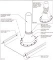
A typical pipe penetration in the field of a metal panel is completed with a flexible, bellows-type boot. The boot should be set over the penetration and installed onto the metal surface. Sealant is applied between the metal panel surface and the metal flange of the pipe boot before fastening the flange to the surface. This application detail is acceptable on all penetrations that are located within the flat part of the panel and can be completed on new and remedial roofing applications.
In situations where the existing penetration is in place and the metal panels cannot be set over it, the new panels may lap around the penetration and a specially designed retrofit pipe boot shall be installed over the existing penetration. The pipe boot installation procedures are similar to the other details; sealant is applied between the boot flange and the metal surface prior to fastener attachment.
In remedial construction installations, penetrations may occur at or near metal ribs. At these locations, fac- tory-fabricated, double-wide metal panels are seamed into the adjacent metal panels. The new seamed metal panel is field-notched at the location of the penetration and end-lapped. The lower part of the seamed panel must also be field-notched to secure around the rib of the adjacent lower panel. Additional structural supports are required to span between the purlins on each side of the penetration. Pipe boot installation is similar to typical penetration details.
Penetrations larger than 18 inches in diameter require special installation procedures. At these locations the penetrations are sealed with a two-piece collar. The sides of the collar are attached to a flashing that is seamed into the panels. Additional structural supports are required to span the purlins at each side of the penetrations. At all applications where new panels are fastened over the existing panels, proper waterproofing of the seams is required. This can be accomplished with specially formulated adhesive and membrane, self-adhered membrane or any other method deemed acceptable by the metal system manufacturer.
Curb installation details are similar to large penetrations. Factory fabricated panels are seamed into the adjacent panels and field-notched at the curb penetration and end lapped. The lower part of the panel is field-notched to secure around the ribs of the lower adjacent panel and is sealed over the back up flashing. Additional structural supports are required.
Roof to Wall Flashings
Most metal roof systems are installed on stand-alone buildings that are designed in a rectangular shape. Typical flashings occur at the ridge vent, gable and eaves. Manufacturers’ specific requirements should be followed at these locations. Flashing installation on metal roof systems is more critical due to the amount of movement that occurs at these areas. Most flashing details include spacer blocks or continuous cleats to accommodate the movement. Butyl tape or sealant is typically applied in these areas.
If properly completed, the typical flashing areas can provide long-term waterproofing protection and trouble at these points will be minimal. Non-typical flashing applications, at adjoining walls, create more concern. Problems at these types of transitions occur because they are rarely completed by most contractors and due to differential movement.
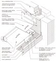
Roof to wall flashings can be designed and applied to accommodate movement. Roof to wall movement joints are designed to allow for thermal movement that is independent of the structural wall. Flashing metal is fabricated that is independent of the metal roof surface and the wall panel. The flashing is applied over the metal surface - extending approximately 4 inches over the surface - which is fastened to the metal surface with an appropriate fastener in accordance with the manufacturer’s required fastening pattern. The flashing is fabricated with a continuous cleat at the mid-point to allow for thermal movement and the subsequent expansion and contraction. The flashing metal is set behind the wall panel and secured to the wall substrate with an appropriate fastener in accordance with the manufacturer’s required fastening pattern.
Waterproofing of the flashing to metal transition can be accomplished with specially formulated adhesive and membrane, self-adhered membrane or any other method deemed acceptable by the metal system manufacturer.
Looking for a reprint of this article?
From high-res PDFs to custom plaques, order your copy today!
.webp?height=740&t=1767036885&width=auto "Header - BE 1170x658 (002).png")

.webp?height=740&t=1755781744&width=auto "KEE(2).png")