Roof Design for Proper Wind Resistance

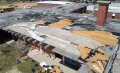
Damage to this Pensacola school building began at the perimeter edges. (Photo courtesy of RICOWI.)
RICOWI inspectors found pressurization and billowing at overhangs and found corrosion had reduced effective uplift resistance at this Pensacola school.
There are four high-wind velocity classifications, which range from 39 mph to in excess of 300 mph. The most common type of wind is a gale force wind, which can vary in wind speed from 39 to 54 mph. Gale force winds are typically steady in velocity and have sporadic gusts. Wind forces in combination with thunder, electric storms and heavy rainfall are referred to as squalls. Squalls can range up to 90 mph. Even though gales and squalls have less wind force of than tornadoes and hurricanes, they contribute to over 70 percent of the wind-related claims per year. This is largely due to their common occurrences in most regions of the United States.
Hurricanes primarily occur in the Gulf and Atlantic costal regions and contribute to widespread damage. Most hurricanes form in the Atlantic as tropical storms; when they exceed 73 mph, they reach hurricane status. There are five levels of hurricanes, which are categorized by wind speeds. Hurricanes typically occur between the end of May and the end of November - the official hurricane season.
Tornadoes are characterized as severe squalls with the addition of a funnel (vortex). Wind speeds are high and typically immeasurable. They have been estimated to be between 200 to 300 mph within the vortex. Tornadoes are most common in the central United States in the spring. However, they can - and have - occurred in other regions at other times of the year.
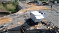
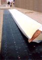
This section of the Edgewater Mall’s roof assembly, photographed after Katrina went
through Biloxi, Miss., held up rather well. (Photo courtesy of CRS Inc.)
In order to properly design for wind attachment, a basic understanding of the effects of winds on buildings is required.
Wind damage to buildings can range from complete demolition of the structure to total or partial roof displacement (blow-off) to damage to penetrations (skylights, mechanical equipment, vents, etc.), doors and windows. Wind failures of roofs generally occur in one of four forms: vortices, interior pressurization, kinetic energy and punctures from wind driven projectiles. The most common form of roof failure from wind effects occurs at perimeter edges. Wind uplift is severe at the roof perimeter, primarily at corners, where it exceeds the normal static pressure against the wall. As air mass from the wind transcends up the building’s perimeter, it forms vortices and creates uplift damage throughout the roof as it flows over and around the building. Proper perimeter edge design and attachment calculations can eliminate these concerns. Research also indicates that the addition of parapet walls with heights of two feet or more can minimize perimeter damage. The parapet wall eliminates the air from flowing over the building, prevents the formation of vortices and reduces wind uplift.
Wind, especially at high velocity, creates a vacuum or negative pressure, lifting the membrane and roof insulation material loose from points of attachment. Interior pressurization can also contribute to wind uplift damage to a roof system.
This is typically created by openings in the building (windows, doors, overhead doors) at the windward side of the building.
In this condition, fast-moving exterior air flows over and around the building, creating a reduced pressure, or suction. The reduced pressure is lower inside the building, which is increased by air flowing through the building openings. When the interior positive pressure is added to negative exterior pressure created by high velocity winds, “ballooning” or uplift of the membrane may occur. The differential pressures are most severe at corners and perimeters. Openings in leeward walls can reduce uplift damage due to internal suction if the wind direction is known.

Installing systems according to the manufacturer´s specifications is essential. (Photo courtesy of Polyglass.)
Attachment design is calculated to prevent uplift damage from these pressures. The equation for kinetic energy is E = ½ M x V2, where “M” equals the mass of air and “V” equals the velocity of the wind.
When determining wind speeds, it is also important to equate the gust factor. Typical weather station instruments only record the “fastest mile” of wind during a storm, not peak gust velocity, which can be considerably greater. An average gust will only blow for a few seconds; however, it could have a great impact in that time frame. For example, the time range for a 70 mph wind to travel one mile is approximately 51 seconds. A 120 mph wind could travel a mile in 30 seconds.
The equation for wind pressure is P = 0.00256 x V2 x G, where “P” = pressure of the wind, “V” = basic wind speed, and “G” = gust factor.
These equations are presented for reference purposes only. Proper roof attachment can be designed through the use of charts and calculations discussed later in this article.
The final and perhaps most prominent roof failure associated with high-velocity winds is membrane impact punctures created by wind-driven projectiles. Analysis of the roof damage created by the hurricanes that hit throughout Florida and the Gulf Coast in 2004 and 2005 indicated a high occurrence of membrane punctures.
The membrane punctures were created by displaced projectiles from the building’s own components (metal coverings, wood, HVAC units, etc.) or from those of surrounding buildings. The membrane punctures contributed to moisture infiltration damaging the roof components (deck, insulation, membrane) and decreasing attachment. In some cases, such punctures contributed to membrane uplift. Once insulation becomes wet, it loses its thermal and structural integrity and it never completely dries out. If the moisture content in the system exceeds the membrane or insulation relative moisture content percentage, then replacement is required.
Older sections of this mall roof sustained damage at the perimeters during Hurricane Katrina.
Roof systems are the largest exterior building component exposed to weather and the elements. The true function of a roof is to protect the building’s interior components from these elements.
We have been trying to perfect this concept since the beginning of mankind, and although we have made great strides in these efforts, once in a while we are reminded that we are fallible. In the summer of 2004, Charley, Francis, Jeanne and Ivan reminded us of some areas that require improvement. If we were not paying attention, Dennis, Katrina, Rita and Wilma reinforced this thought process in 2005.
Catastrophic losses in the United States from hurricanes in 2004 and 2005 ($23 billion and $53 billion, respectively) were the highest since Hurricane Andrew in 1992 ($20.5 billion).
The coming years may provide further reminders. Meteorologists are projecting that there will be an increase in hurricane activity well into the next decade.
Many experts believe we are currently in a weather pattern that evolves in 30 to 40 year spans. These cycles have been well documented and can be charted from the early 1900s through today. The last intense hurricane cycle ended in the late 1960s and included the recently well-publicized Camille, which hit New Orleans in 1969. Hurricane activity was not as frequent in the time period between the early 1970s and 2003. However, hurricanes of significance did occur in this time period.
In the late 1980s and early 1990s, two hurricanes (Hugo and Andrew) had a significant impact on the United States roofing industry. The destruction of roofs associated with these hurricanes forced insurance companies to start mandating roof designs that could withstand wind uplift forces. A study conducted after Hurricane Hugo hit South Carolina in 1988 found that the majority of wind uplift damage was initiated at the perimeter edge. In response to this study, Factory Mutual published a technical bulletin detailing proper roof edge and flashing design. The industry and most roofing manufacturers immediately implemented FM’s design guidelines as requirements, and they are now standard guidelines for roof design.
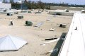
The building´s height, roof area and perimeter construction must be considered for proper roof design. (Photo courtesy of Polyglass.)
A requirement of the code is that wind uplift design review is completed and certified for all roofing projects (new and remedial) in this region. The required construction permits are not provided without these certifications. In addition to this requirement, all roofing material manufacturers must test their systems for wind-uplift compliance to provide materials in the region. The wind uplift testing for the “Notice of Acceptance” rating is required in addition to any standard Factory Mutual testing that the manufacturer may have already conducted.
As was the case with Hugo, the requirements established after Andrew were initiated after billions of dollars in roof-related damage claims were paid.
What should we expect after the hurricanes of 2004 and 2005? Further changes to the building codes related to roof attachment in high-velocity wind zones can be expected.
The primary reason that proactive codes are required is that the seven most recent hurricanes all occurred in areas outside of the current high-velocity wind code zones. Furthermore, Charley, Ivan and Katrina created substantial destruction in inland areas. With the further threat of more frequent severe storms in the next decade, it is likely that authorities in the Gulf Coast states, Central Florida and the Florida Panhandle are currently discussing this issue. In fact, some of the current restoration work on buildings damaged in these storms is being completed in accordance with regulations provided in the high-velocity wind zone section of the Florida Building Code, even though the current codes do not require it.
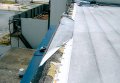
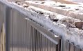
Perimeter roof damage is evident in this section of the Edgewater Mall in Biloxi.
The procedure to determine wind uplift pressures on specific buildings during the design phase is based a calculation that takes into account the basic wind speed in the geographical area, the ground surrounding the building and the roof uplift pressure at the field of the roof. The building’s height, roof area dimensions and perimeter construction are also considered. It is the responsibility of the designer to complete these calculations to determine the proper wind uplift pressures for the building.
The calculated pressure is applicable for the determination of the entire roof system, including the roof deck and all above-grade components. However, this procedure only determines attachment rates for the field of the roof. The pressures required for corners and perimeters must be calculated separately. The roof wind uplift calculation is based on four factors:
- Basic wind speed.
- Ground roughness coefficient.
- Roof uplift pressure.
- Adjustments to uplift pressures.
Basic Wind Speed
Basic wind speed is determined by reviewing a wind speed map of the United States. The chart provides the annual extreme wind speeds in each state for a 100-year period. The wind speed provided is based on a height of 30 feet above the ground. The wind speed provided for the calculation should be within five miles of the wind speed of the geographic location of the building. An additional ten miles should be added to the wind speed in areas of extreme local winds.

Attachment procedures differ depending on the type of deck and roof system components. (Photo courtesy of Polyglass.)
The ground roughness coefficient is the general terrain around the building location. There are three ground roughness coefficient categories - B, C, and D. Category B is typical urban and suburban areas. Category C is open terrain with surrounding buildings less than 30 feet in height and Category D is for areas extending 1,500 feet in shore from a body of water. The most extreme category must be used even if it is only true at one side of the building.
Roof Uplift Pressure
Roof uplift pressure is determined through the use of a chart based on the height of the building, the wind exposure zone and the proper ground roughness coefficient category.
Adjustments to Uplift Pressures
The calculations require the adjustment of uplift pressures based on openings in the floor below the roof surface, glass and door size openings and building use. Public buildings that occupy in excess of 300 people at any given time have a higher safety factor than perimeter dwellings. The calculations provide proper attachment requirements of the roof system to the substrate. The attachment procedures differ based on the type of deck and roof system components. It is the designer’s responsibility to determine proper attachment procedures.
Looking for a reprint of this article?
From high-res PDFs to custom plaques, order your copy today!
.webp?height=740&t=1767036885&width=auto "Header - BE 1170x658 (002).png")

.webp?height=740&t=1755781744&width=auto "KEE(2).png")