Fighting for City Hall
When they say “You can’t fight city hall,” they aren’t
talking about Mother Nature. And she’s been fighting Milwaukee City Hall
for a long time.

When they say “You can’t fight city hall,” they aren’t talking about Mother Nature. And she’s been fighting Milwaukee City Hall for a long time.
 Moisture infiltration had been a problem since its initial construction,
and by 2001 significant deterioration was evident in the structure and envelope
materials. Damage included corroded steel framing, deteriorated masonry and stained
interior finishes. Furthermore, large loads from the clock gables and the
masonry’s own weight had caused stress cracks to open in the walls of the South Tower.
Moisture infiltration had been a problem since its initial construction,
and by 2001 significant deterioration was evident in the structure and envelope
materials. Damage included corroded steel framing, deteriorated masonry and stained
interior finishes. Furthermore, large loads from the clock gables and the
masonry’s own weight had caused stress cracks to open in the walls of the South Tower.
Engineering firm Simpson Gumpertz & Heger Inc. (SGH) was called in to assess the damage in the spring of 2001. SGH, the historic preservation and building envelope consultants and structural engineer of record, and Engberg Anderson, the lead local architect, pored over the results of the damage reports prepared by SGH, Wiss Janney Elsner of Chicago, and others. They devised a plan to stabilize and restore the historic structure, and their team was selected by the city to repair City Hall in 2003. Over the next five years, a team of engineers, architects, roofing contractors and specialized craftsmen worked to painstakingly restore the building. The goal was to accurately replicate the damaged elements and ensure the building would remain watertight for decades to come.
Gabby noted there had been several attempts to remedy these problems in the past. “According to historic records with the city, the building underwent a major restoration program about every 25 years since original construction to try to remediate cracking and water infiltration,” he said. “The earliest documentation of repairs that we found was dated 1909.”
 SGH was able to identify the structure’s problems through
interior and exterior observations, openings in exterior walls, water testing
to determine leak sources, and building movements to confirm the results of the
finite element analysis of the South
Tower. “Using vibrating
wire strain gages and thermal couples, we recorded field data for a year and
downloaded this information remotely from our office in Waltham, Massachusetts,
via cellular phones,” said Gabby. “In this fashion, we were able to monitor
building movement and cracking daily.”
SGH was able to identify the structure’s problems through
interior and exterior observations, openings in exterior walls, water testing
to determine leak sources, and building movements to confirm the results of the
finite element analysis of the South
Tower. “Using vibrating
wire strain gages and thermal couples, we recorded field data for a year and
downloaded this information remotely from our office in Waltham, Massachusetts,
via cellular phones,” said Gabby. “In this fashion, we were able to monitor
building movement and cracking daily.”
Even with the detailed damage reports, team members could not be sure exactly what they would find when demolition began, according to Engberg Anderson project architects Kevin Donahue and Daniel Kabara. “We believed we had a good handle on the work, but despite all of the exploratory openings, we knew other things would be found,” Kabara said. “Given the rate of continued deterioration, by the time construction started, conditions would be worse than at the time of assessment.”
As the project began, the team had to envision several possible solutions to various problems depending on the actual conditions. “Because there was limited access to the building, a lot of solutions were set up as proposed solutions,” Donahue said. “We knew we’d be tweaking the solutions in the field.” Full access to the building wasn’t possible until the scaffolding was completed. The scaffolding itself was a huge task. “Pipe staging could only rise up to the 12th floor because of height restrictions,” said Gabby. “Above this level at the South Tower, pipe scaffolding was primarily supported on temporary deep girders that cantilevered beyond the exterior face of the tower at the belfry level.”
The site itself posed other challenges. Milwaukee City Hall is a fully functioning governmental building that had to stay open throughout the course of the project.
Tunnels and walkways protected pedestrians and kept foot traffic flowing. Sidewalks that ran above hollow vaults had to be shored up from below. The busy streets that ran alongside the building could only be closed for brief periods.
Everyone involved noted that safety was the top priority. “The one thing everyone agreed on at all times on the project is that safety comes first,” Donahue said. “You have to know what’s around you and what’s going on, because there are no little accidents that high in the air.”

The building was taken apart piece by piece. Terra cotta elements were shipped to California to be reproduced by Gladding McBean and Co. The replacements for the larger-than-life terra cotta lion heads weighed in at roughly 900 pounds each.
“It was originally built in 1893 without scaffolding,” said Donahue. “It was built from the inside out. The terra cotta was built into the walls - a 2-foot-by-3-foot-by-2-foot hollow section was placed in the brick and bricked in. In many of the repairs, we didn’t have the luxury of removing material that held it in place. You had to develop methods for securing that piece that we couldn’t predict in advance.”
Shop drawings were produced to cover proposed methods of attachment, including hooks that tied into the brick and clamps that held the terra cotta in place. Some elements, like a terra cotta lintel, were pre-assembled on the ground and hoisted into place.
Before that took place, the South Tower had to be shored up. “For the most part, cracking of the South Tower was due to the geometry of the tower and its own dead weight, which resulted in high-tensile stresses above flat arches and semi-circular arches,” said Gabby. To give the tower increased tensile capacity, a reinforced concrete ring beam was installed at the 13th floor. Precast concrete backup with masonry veneer was installed in lieu of solid masonry to lighten the dead load of the large clock gables.
“Rubberized asphalt peel-and-stick membrane was installed over backup masonry or concrete with lead-coated copper flashings at strategic locations throughout the walls to drain water to the exterior,” said Gabby.
A mix of 24-ounce and 32-ounce copper was used on the tower. “It’s heavier than you would normally see,” said Donahue. “It’s 300 to 400 feet up, on a lakefront in the upper Midwest with snow, high winds, driving rain and hail.”
“The previous roof was torn to shreds,” said Kabara. “The copper had gaping holes in it. Granted, it was some 70 years old, but it was greatly deteriorated. Over the years it had let a lot of water in.”
Some of the steel beneath the copper sheathing was not only deteriorated - it had been eaten away completely. “Some of the steel was 100 percent gone,” Kabara said. “Some of the main beams supporting the structure were gone.”
The copper work was expertly handled by F.J.A. Christiansen Roofing of Milwaukee. A crane could not be used, and heavy copper pieces had to be handled with care. “Workers had to carry pieces up by hand,” said Kabara. “The most dramatic one is the 36-inch sphere that was carried up a ladder by hand and put in place on the 40-foot flagpole atop the spire.”
For the flat roofs, an SBS modified bitumen was chosen to replace the existing BUR and EPDM roofs, which were torn off, exposing the clay book tile underneath. Work on the low-slope roofs was handled by F.J.A. Christiansen and Roberts Roofing & Siding Inc. of Milwaukee, while the slate mansard roof was restored by Pennebaker Enterprises of Milwaukee. The job was completed on time and on budget, and the project has garnered some 13 local and national awards.
“One of the important factors on this job was really understanding the historic methods and materials and working with them, rather than just superimposing modern materials,” said Donahue. “We relied on traditional methods of construction and careful integration of flashings and water management. We had to develop a restoration strategy at the beginning of the project. We weren’t going to rebuild the building, but restore it.”
“They say you can’t build them like you used to,” Kabara said. “But you can build them like they used to if you have the skills - or develop them. That’s what happened here. The craftsmen really took ownership of the project.”

“The design incorporated new metal flashings at areas such as over new relieving angles and beneath curving terra cotta at dormers,” Gabby said. “By locating new relieving angles at steps in the masonry veneer, the flashing drip edge was typically hidden in a shadow line and difficult to detect.”
Built-in gutters above the 7th floor of the main building were first covered with peel-and-stick rubberized asphalt membrane, and then fully lined with lead-coated copper over rosin paper. “Thirty-two ounce copper was installed due to the relatively long distance between expansion joints (which was dictated by building geometry) and the location of existing down leaders,” Gabby said. “Other than expansion joints, all metal flashing joints (at changes in profile and between adjoining pieces of flashing) were fully riveted and soldered watertight. Expansion joints were made watertight by stripping-in the joints with EPDM membrane (flashing laps did not rely on sealant for watertightness).”
When they say “You can’t fight city hall,” they aren’t talking about Mother Nature. And she’s been fighting Milwaukee City Hall for a long time.
Originally constructed in 1896, Milwaukee City Hall
was designed by H.C. Koch in the German Renaissance Revival style. A registered
National Historic Landmark and a Milwaukee
icon, the building is clad with granite, sandstone, brick, and architectural
terra cotta. Its slate mansard roof features gabled dormers, and a large
skylight in the flat portion of the main roof floods the eight-story building
atrium with natural light. At the south end of the building, the masonry clock
tower rises to a height of 393 feet, where it is capped by a copper-clad spire.
Engineering firm Simpson Gumpertz & Heger Inc. (SGH) was called in to assess the damage in the spring of 2001. SGH, the historic preservation and building envelope consultants and structural engineer of record, and Engberg Anderson, the lead local architect, pored over the results of the damage reports prepared by SGH, Wiss Janney Elsner of Chicago, and others. They devised a plan to stabilize and restore the historic structure, and their team was selected by the city to repair City Hall in 2003. Over the next five years, a team of engineers, architects, roofing contractors and specialized craftsmen worked to painstakingly restore the building. The goal was to accurately replicate the damaged elements and ensure the building would remain watertight for decades to come.
The Game Plan
According to Brent Gabby, Senior Principal at SGH, the project’s phases included controlled demolition and reconstruction of the South Tower masonry above the 12th floor; repairs to corroded steel truss elements; rehabilitation of deteriorated brick and terra cotta elements; restoration of the existing windows; installation of the waterproofing materials at windows, walls, dormers and gutters, and restoration of the existing slate, copper, and membrane roofs.Gabby noted there had been several attempts to remedy these problems in the past. “According to historic records with the city, the building underwent a major restoration program about every 25 years since original construction to try to remediate cracking and water infiltration,” he said. “The earliest documentation of repairs that we found was dated 1909.”
Even with the detailed damage reports, team members could not be sure exactly what they would find when demolition began, according to Engberg Anderson project architects Kevin Donahue and Daniel Kabara. “We believed we had a good handle on the work, but despite all of the exploratory openings, we knew other things would be found,” Kabara said. “Given the rate of continued deterioration, by the time construction started, conditions would be worse than at the time of assessment.”
As the project began, the team had to envision several possible solutions to various problems depending on the actual conditions. “Because there was limited access to the building, a lot of solutions were set up as proposed solutions,” Donahue said. “We knew we’d be tweaking the solutions in the field.” Full access to the building wasn’t possible until the scaffolding was completed. The scaffolding itself was a huge task. “Pipe staging could only rise up to the 12th floor because of height restrictions,” said Gabby. “Above this level at the South Tower, pipe scaffolding was primarily supported on temporary deep girders that cantilevered beyond the exterior face of the tower at the belfry level.”
The site itself posed other challenges. Milwaukee City Hall is a fully functioning governmental building that had to stay open throughout the course of the project.
Tunnels and walkways protected pedestrians and kept foot traffic flowing. Sidewalks that ran above hollow vaults had to be shored up from below. The busy streets that ran alongside the building could only be closed for brief periods.
Everyone involved noted that safety was the top priority. “The one thing everyone agreed on at all times on the project is that safety comes first,” Donahue said. “You have to know what’s around you and what’s going on, because there are no little accidents that high in the air.”
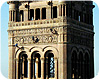
This view of the Milwaukee City Hall South Tower shows the
terra cotta lion heads below the clock face. Photo by Eric Oxendorf.
A Lot of Terra Cotta
The first step after the scaffolding was set up was to document the building’s external features so it could be put back together properly. “Before we began demolition, one important thing was to remove a sample set of decorative elements so they could be reproduced,” Kabara said.The building was taken apart piece by piece. Terra cotta elements were shipped to California to be reproduced by Gladding McBean and Co. The replacements for the larger-than-life terra cotta lion heads weighed in at roughly 900 pounds each.
“It was originally built in 1893 without scaffolding,” said Donahue. “It was built from the inside out. The terra cotta was built into the walls - a 2-foot-by-3-foot-by-2-foot hollow section was placed in the brick and bricked in. In many of the repairs, we didn’t have the luxury of removing material that held it in place. You had to develop methods for securing that piece that we couldn’t predict in advance.”
Shop drawings were produced to cover proposed methods of attachment, including hooks that tied into the brick and clamps that held the terra cotta in place. Some elements, like a terra cotta lintel, were pre-assembled on the ground and hoisted into place.
Before that took place, the South Tower had to be shored up. “For the most part, cracking of the South Tower was due to the geometry of the tower and its own dead weight, which resulted in high-tensile stresses above flat arches and semi-circular arches,” said Gabby. To give the tower increased tensile capacity, a reinforced concrete ring beam was installed at the 13th floor. Precast concrete backup with masonry veneer was installed in lieu of solid masonry to lighten the dead load of the large clock gables.
“Rubberized asphalt peel-and-stick membrane was installed over backup masonry or concrete with lead-coated copper flashings at strategic locations throughout the walls to drain water to the exterior,” said Gabby.
Workers survey the outside walls of the South Tower.
Photo courtesy of Simpson Gumpertz & Heger Inc.
Restoring the Roof Systems
Ornate copper elements topping the towers were removed individually, and many had to be recreated by Heather & Little, Ltd., Markham, Ontario. The South Tower posed an additional challenge, as it sustained significant damage in 1929 when lightning struck it, causing a fire. “It was burned back to its structural steel,” Donahue said. “It was repaired, but they simplified and excluded a number of details. As a result, we knew where stuff went - we had original building drawings - but we had to study historical photos to get all of the details right.”A mix of 24-ounce and 32-ounce copper was used on the tower. “It’s heavier than you would normally see,” said Donahue. “It’s 300 to 400 feet up, on a lakefront in the upper Midwest with snow, high winds, driving rain and hail.”
“The previous roof was torn to shreds,” said Kabara. “The copper had gaping holes in it. Granted, it was some 70 years old, but it was greatly deteriorated. Over the years it had let a lot of water in.”
Some of the steel beneath the copper sheathing was not only deteriorated - it had been eaten away completely. “Some of the steel was 100 percent gone,” Kabara said. “Some of the main beams supporting the structure were gone.”
The copper work was expertly handled by F.J.A. Christiansen Roofing of Milwaukee. A crane could not be used, and heavy copper pieces had to be handled with care. “Workers had to carry pieces up by hand,” said Kabara. “The most dramatic one is the 36-inch sphere that was carried up a ladder by hand and put in place on the 40-foot flagpole atop the spire.”
For the flat roofs, an SBS modified bitumen was chosen to replace the existing BUR and EPDM roofs, which were torn off, exposing the clay book tile underneath. Work on the low-slope roofs was handled by F.J.A. Christiansen and Roberts Roofing & Siding Inc. of Milwaukee, while the slate mansard roof was restored by Pennebaker Enterprises of Milwaukee. The job was completed on time and on budget, and the project has garnered some 13 local and national awards.
“One of the important factors on this job was really understanding the historic methods and materials and working with them, rather than just superimposing modern materials,” said Donahue. “We relied on traditional methods of construction and careful integration of flashings and water management. We had to develop a restoration strategy at the beginning of the project. We weren’t going to rebuild the building, but restore it.”
“They say you can’t build them like you used to,” Kabara said. “But you can build them like they used to if you have the skills - or develop them. That’s what happened here. The craftsmen really took ownership of the project.”
Sidebar: Water Management
Water intrusion had taken an obvious toll on the building throughout its more than 100 years of service, and a key goal of the restoration project was to minimize such problems in the future. “From a design perspective, the biggest challenge was improving the water management characteristics of the walls by converting the mass masonry walls to cavity walls where we could and adding a backup waterproofing membrane and flashings, while still maintaining the original aesthetic,” said Brent Gabby, Senior Principal of Simpson Gumpertz & Heger Inc. (SGH). “Another challenge was coordinating shop drawings between different trades and similarly integrating different systems in the field to maintain waterproofing continuity.”“The design incorporated new metal flashings at areas such as over new relieving angles and beneath curving terra cotta at dormers,” Gabby said. “By locating new relieving angles at steps in the masonry veneer, the flashing drip edge was typically hidden in a shadow line and difficult to detect.”
Built-in gutters above the 7th floor of the main building were first covered with peel-and-stick rubberized asphalt membrane, and then fully lined with lead-coated copper over rosin paper. “Thirty-two ounce copper was installed due to the relatively long distance between expansion joints (which was dictated by building geometry) and the location of existing down leaders,” Gabby said. “Other than expansion joints, all metal flashing joints (at changes in profile and between adjoining pieces of flashing) were fully riveted and soldered watertight. Expansion joints were made watertight by stripping-in the joints with EPDM membrane (flashing laps did not rely on sealant for watertightness).”
Looking for a reprint of this article?
From high-res PDFs to custom plaques, order your copy today!
.webp?height=740&t=1767036885&width=auto "Header - BE 1170x658 (002).png")

.webp?height=740&t=1755781744&width=auto "KEE(2).png")