Testing,Testing
Field Testing and Material Testing
Testing is playing an increasingly larger role in the design and construction of building exterior components. In most cases, proper testing goes hand in with hand with project success. Test methods can be employed during the design stage to determine the correct system and during the construction phase to ensure proper specification compliance. Testing can be conducted through two methods: field testing and material testing These methods can be conducted at all building envelope components from below-grade waterproofing to exterior walls, sealants and roofs. This article will focus primarily on the roof component. The most effective conclusions are drawn when both methods are applied in tandem on a project.Field testing is completed through a thorough inspection of the required component to determine specific site conditions necessary for proper design. Testing should be conducted on both new construction and remedial roof projects, with proper tests performed in each instance to derive the required information.

Tensile and elongation testing.
On remedial roof projects, all aspects of the component are investigated to determine the condition of the existing roof. The exact condition of the existing system should be determined in order to decide the proper materials and systems required in the remedial design. It is important to review the existing roof so that conditions that led to the detriment of the roof's service life are not repeated.
Regardless of the membrane covering, all roof systems are comprised of similar components. The materials for the components are the only variations. The roof system components are:
- Structural deck (substrate).
- Insulation.
- Membrane.
- Surfacing.
- Flashings.
- Metal terminations.
Critical elements to the success of a roof system include proper attachment methods and sufficient drainage. Prior to design and system allocation, two critical calculations should be performed: a wind uplift calculation and a drainage calculation. A wind uplift calculation will determine the proper attachment methods for the roof at the specific location. Wind uplift calculations take into account such conditions as basic wind speeds for the geographic area in which the building is located, conditions surrounding the building and exposure to the public. The calculation determines the external coefficient factor for the building and provides proper attachment rates and methods. It is also important to complete a perimeter edge calculation to determine proper attachment of components at the most vulnerable point of the building for wind uplift damage. The base perimeter nailer should be anchored to the structural component - not the deck - with anchors or expansion bolts.
Drainage calculations are completed to determine the capacity of the roof area for drainage. Capacity is to be determined in accordance with the local codes. The calculations are completed by determining the slope of the deck, the total roof area and the total area of any adjacent areas that will contribute water flow to the area. The type of edge construction should be considered.
If there is a perimeter edge, then water flow can be directed to exterior gutters. If there is a parapet wall, then the height of the wall and mean height are required. The rainfall rate for the geographic location is also required to determine drainage capacity. The rainfall rate is based on the rain intensity of 5 inches per hour.
There are two different types of roof drainage points that require design: primary and secondary. Primary drains are designed to accommodate the full capacity of water flow from the roof system. Secondary drains are provided as overflow drains. Secondary drains can be provided as internal drains that connect to a separate lead than the primary drains (in case of pipe blockage to the main drain).
Secondary drainage can also be provided as scuppers in parapet walls. Scupper design should determine the number of scuppers required for overflow and the proper height and width to accommodate capacity. If scuppers are provided as primary drainage, then they should be flush with the roof level and a minimum of 4 inches in height. If they are provided for overflow, than the scuppers must be a minimum of 2 inches above the roof surface and a minimum of 4 inches in height and width. All secondary drains must be within the proper distance of the primary drains to accommodate a hydraulic head of four 4 inches in depth.
The roof’s material components must be thoroughly examined.
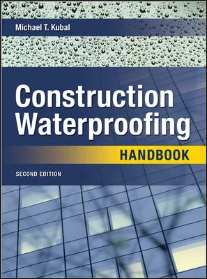
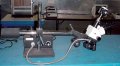
Field withdrawal resistance tests or fastener pull tests are conducted to determine if the proposed mechanical fastener provides sufficient static uplift force for attachment of the specific component to the substrate. These types of tests can be conducted on underlayment's, insulation and mechanically attached membranes.
The equipment used to conduct pull tests has a mechanically operated dynamometer (pull tester) with a hydraulic gauge cell to measure the force of the pull. The gauges are operated with a screw or pump handle at a regulated rate depending on the type of deck.
Pull tests are conducted at the rate specified by the local building code. Typical codes require 10 pulls for the first 100 squares and three pulls for every additional 50 squares. Pulls are required in the field, at the perimeter and the corner of each roof area. Tests shall be conducted in all separated (parapet wall, expansion joints, etc.) roof areas and at all roof areas with different types of decking.
The statistical analysis of the completed pulls is tabulated, and if the test average exceeds the mean failure load for the deck, the fastener is acceptable for use. Tile uplift tests are completed on newly applied mortar or adhesive set and mechanically attached tiles. Testing is completed with a hand-gripping device that consists of a hook shaped to a 90- degree angle that slides under the nose of the tile and remains in place as the load is applied. The hook shall have sufficient strength to resist applied loads of up to 100 foot-pounds. On mortar- or adhesive set tiles, the tile must surpass a static test upload of more than 35 foot-pounds per tile. On mechanically attached tiles, the minimum static test uplift load must be more than 80 percent of the resistance load listed in the manufacturer's product approvals. A minimum of one tile in every 10 shall be tested in the field of the roof, and a minimum of one in five shall be tested at the perimeter and corners. A minimum of 97 percent of the tiles that are tested must be fully bonded.
It would be beneficial to provide quality assurance inspections throughout the course of the project, on a full-time or part time basis. If this is not completed, then at the very least phase inspections should be completed throughout the course of the project to ensure specification compliance. Inspections are required for all roof projects (new or remedial, residential or commercial) at three critical application points: tin cap inspections, mop-in-progress and final inspection.
Tin cap inspections are conducted to verify compliance of the underlayment attachment to the structural deck. These inspections are critical to success of the system because of the vulnerability of wind uplift at these locations. The inspection is conducted by reviewing the completed mechanical attachment rates and patterns at the field, corners and perimeter areas. The fastening patterns are determined by the wind uplift calculations completed for the project should be in compliance with the manufacturer’s requirements for the substrate. In addition to reviewing patterns and rates, the inspector should verify that the proper fasteners/nails and plates are applied.
Mop-in-progress inspections are conducted during the installation of the membrane to verify compliance of application with the specifications and/or the manufacturer’s requirements. Final inspections are conducted to determine full project compliance. A thorough inspection of the roof system, flashings, penetrations and metal components is required. Knowledge of the applied material manufacturers products and application procedures, as well as practical roofing experience is required to conduct these inspections.
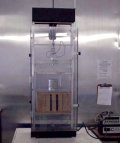
Tensile and elongation testing apparatus.
Material testing identifies the types of materials applied in the construction of the building’s exterior components and, more importantly, it identifies the quantities of materials applied in construction. In the United States, construction material testing is conducted in accordance with the testing procedures established by the American Society of Testing Materials (ASTM).
ASTM is comprised of several subcommittees that work within each building component discipline to develop and update testing standards and procedures for all materials. The subcommittees are comprised of industry professionals, primarily manufacturers, who work on these efforts on a volunteer (nonpaying) basis. In roofing, material testing is conducted on test cuts (roof samples) that are extracted from the completed roof system.
In the construction phase, testing is conducted on the extracted samples because visual inspections have their limitations and the only way to effectively determine the true construction of a roof system is by extraction of a test cut. The test cut will provide evidence of the material used and application procedures.
A test cut will also reveal if the as built roof system was constructed in accordance to the proper design and specification. The extraction process of test cuts is similar if the sample is to determine construction or condition of the roof system.
The differences are in the type of forensic testing that is conducted on the test samples. In a maintenance inspection, the sample test cuts are extracted to determine both the construction and condition of the existing roof system. For these purposes, the test cuts can be completed in the following manner for all types of roof systems:
1. Identify the appropriate location of the test cut. The proper area should be representative of the entire roof area construction. Do not take a test cut at a previously repaired area.
2. Take one test cut per representative roof area. Facilities with multiple roof areas and/or multiple roof systems require one test cut per roof area.
3. Identify the location(s) of the test cut(s) on the roof plan.
4. Use a 12-inch by 12-inch template and measure the area to be cut to the proper length.
5. On bituminous roof systems with poured aggregate, spud off the existing aggregate and flood coat down to the existing membrane. Make certain the existing membrane is not damaged during this process.
6. Following the established 12-inch by 12-inch pattern, cut the membrane, any insulation(s) and underlayment(s) to the structural deck. Single-ply systems can be cut with scissors. Bituminous roof systems require a box cutter, knife or hatchet.
7. Remove all roof system components (membrane, insulation and underlayment) from the opening.
8. Photograph the system components and structural deck substrate.
9. Record system construction components identifying the method of attachment of each component, including:
- Deck type.
- Underlayment (if used).
- Insulation type, thickness and condition (each layer).
- Method of insulation attachment (each layer).
- Membrane type, thickness and condition.
- Method of membrane attachment.
- Type of surfacing and method of attachment.
- Is there moisture present in the system?
- Is there structural delamination of the component?
- Is there indication of deck delamination?
12. Depending on the type of system, properly repair the sample opening in the manner outlined below.
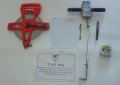
Gauges used to conduct tile uplift tests.
1. Clean and dry surfaces approximately 12 inches to either side of the damaged area. On aggregate-surfaced roofs, the surfacing should be chipped away down to the felts.
2. Prepare surfaces with brush application of bituminous primer. This penetrates loose dust, etc., and promotes adhesion.
3. Apply mastic.
4. Embed recommended patching fabric. Each layer should extend 2 inches further onto existing membrane.
Thermoplastic (PVC) Membrane
1. Clean and wipe with solvent if necessary to remove contaminants.
2. Apply solvent to clean, dry surfaces only, in dry weather. Alternate system uses heat welding, which may be more reliable in damp or cold weather.
3. Embed new film immediately. After solvent evaporates and the film cools, inspect carefully with a blunt tool to be certain edges are sealed.
4. Use heat gun and roller to seal any loose edges.
5. Caulk all exposed edges with appropriate caulk.
Modified Bitumen Membrane
1. Remove damaged material and clean surfaces to be bonded.
2. Prime with bituminous primer.
3. Apply special mastic where recommended. In some, cases, ordinary bituminous mastic is acceptable. Refer to literature for correct materials and reinforcements.
4. Many systems can be torched with propane torch. Caution: Use appropriate equipment. Keep a fire extinguisher handy. Technique requires experience to “flux” old and new materials together, followed by pressure on spatula or flat edge of knife to ensure adhesion. Too much heat may melt reinforcement.
5. Resurface as required.
Elastomeric Sheets (EPDM)
1. Clean surfaces.
2. Abrasion with wire brush, sandpaper, etc. may be necessary to roughen surface and remove surface oxidation.
3. Use primer where specified.
4. Apply “contact” cement to both surfaces to be bonded. Allow it to dry until light finger touch is tacky but adhesive does not transfer to finger.
5. Carefully embed new membrane, starting at one side only, so all air is expelled in front of the membrane.
6. Press firmly. Roll with hard roller.
7. Inspect laps and reseal as needed.
8. Caulk edges with elastomeric caulking.
9. Resurface to match rest of system.
Elastomeric (Liquid-Applied) Systems
1. Clean surfaces and abrade to remove oxidation.
2. Apply brush coat of base material. For example, in neoprene-Hypalon systems, the base coat is black neoprene.
3. While tacky, lay repair fabric into base coat and firmly embed. Apply more base coat to thoroughly impregnate fabric. Allow it to dry.
4. Apply additional coats of base and color coat until mil thickness matches original membrane.
5. Embed granules or grit into final coat to match the rest of the system.
Cured Hypalon
1. Clean with detergent and rinse completely.
2. Liberally apply recommended solvent.
3. Prime with Hypalon primer.
4. Heat weld the repair material.
5. Probe all edges of patch.
Sprayed Polyurethane Foam
1. Clean surfaces and remove damaged material.
2. Trim exposed foam in fracture to obtain clean foam surface to depth of penetration. Splices of 1/8 inch to 1/4 inch are adequate to provide suitable foam surface for patch. Bevel cut edge at approximately a 45-degree angle around perimeter of opening to depth of penetration.
3. Brush back loose granules and abrade coating around penetration.
4. Use Froth Pak, or take two cups, one each marked A and B. Fill A to 40 percent of volume with the isocyanate component and cup B to 40 percent of volume with the polyol component.
5. Gradually pour contents of cup A into cup B while stirring with wooden tongue depressor or spatula. Continue stirring the combined material for approximately 30 to 40 seconds or until mixture begins to show a color change that indicates incipient foaming.
6. Gradually pour foaming mixture over prepared areas as follows: Begin by pouring material onto beveled cut foam edge in order to wet out as completely as possible, then distribute remaining material evenly over bottom of the penetration or repair area.
7. Permit the foam to rise and set. Allow in-place foam to cure for a minimum of half an hour.
8. If repair area is under-filled, a second or third pour may be required to completely fill the void. Note: With experience, it will be found that quantities of the foam system can be varied to match size of repair.
9. If second or third pour is required, pour(s) can be made as soon as foam is tack free (four to five minutes) without waiting for a half-hour cure period.
10. Once foam in filled void is cured, trim away excess foam with serrated knife, saw or grinder to level of adjacent roof. Remove all foul dust and/or bits prior to application of coating.
11. Following above steps, brush coats of protective coating can be applied for completion of the repair. It is recommended that a total of 25 to 30 mils wet coating be brush-applied over the repair area, using a two-coat procedure. A minimum of four to six hours drying time should be allowed between coats. Further, the same drying time should be permitted after application of the final coat prior to subjecting the repaired area to foot traffic.
12. Put the extracted sample in a properly sealed bag.
13. Identify the samples with the following information:
- Building name and address.
- City and state.
- Sample identification.
- Date of inspection.
- System construction.
- Temperature at time of inspection.
15. Make certain that all of the sample bags are properly sealed for transport to the testing laboratory.
16. Prior to leaving the roof area, make certain that all test-cut locations are properly repaired and watertight.
Microscopic examination assists in material evaluation.
Immediately after the test-cut location is properly repaired, the inspector should prepare a written analysis of the conditions observed in the field. The following information should be documented:
- How many membranes are there?
- Record the condition of the deck. For example, do metal decks indicate rusting? Has lightweight concrete suffered moisture induced degradation? Is wood deck split?
- Is there an attached underlayment?
- Is the insulation well adhered to the substrate (deck or bottom layer of insulation)?
- Is the insulation wet or deteriorated?
- Does the membrane show signs of deterioration?
Once the samples have been extracted from the system, they must be properly packaged and transported to a testing laboratory. There are a number of tests that can be performed on the samples depending on the information that is required. Testing conducted for new roof applications should focus on system construction and application methods. Tests can be conducted on all roof system components.
Membrane Tests
The service life of a roof system depends on the condition of the roof membrane. Surface defects can be identified by the visual observations conducted in the inspection phase; however, the true condition of the membrane can only be identified by physical tests conducted in a laboratory.
Each type of roof membrane has its own failure modes. Therefore, the laboratory testing differs for each type of roof membrane system.
Built-Up Roof Systems
Built-up roof systems are primarily constructed on site and application procedures and material quantities are vital to the overall success of the roof system. It is due to this fact that the majority of ASTM roof tests apply to built-up roof systems. For the overall analysis of the system, and more importantly, the deformation of the remaining service life, the following test methods are required.
In all built-up roof test procedures, the membrane must be separated into the individual ply configuration. When separating the plies of the membrane, important information can be obtained by observing the apparent condition of the materials and the nature of the bond between the plies. During the separation process, the number of plies should be recorded, as well as ply arrangement, lap placement and the headlap spacing. The separated plies should be inspected for irregularities, such as voids or dry spots on the felt surface.
The sample sizes may differ depending on the type of information that is required. As a general rule of thumb, sample sizes can be determined as follows:
- For failure investigations and lap placement, cut the sample 4 inches by 40 inches across the laps of the membrane.
- For weight verification, cut the samples 12 inches by 12 inches.
- For failure investigations and deck inspections, cut the sample 24 inches by 24 inches or larger.
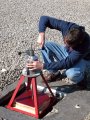
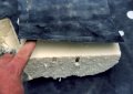
Type and quantity of interply bitumen.
The most comprehensive test for built-up roof systems is ASTM D 2829 “Standard Practice for Sampling and Analysis of Built- Up Roofs.” This test can be completed for built-up roof systems with coal tar or asphalt bitumen. The conclusion of this test provides a report analyzing the tested roof system. ASTM requires the following report of laboratory analysis:
1. Describe the built-up roof, including the type and class of bituminous material, type of surfacing, type of insulation, type of roof decking, and the type and number of felts or roofing sheets.
2. Fully identify the origin and roof location of each specimen.
3. Report the mass per unit area of surfacing, average interply bituminous material, top coating bituminous material, and the total specimen (minus insulation).
4. Diagram the felt lapping to show the number of plies and the lap relationships it determined.
The test cut analysis will provide considerable information relating to the future performance capacity of the existing roof system. When completing the laboratory analysis, there are a number of common workmanship errors that can be identified in these tests. These workmanship errors decrease the service life of built-up roof systems. The laboratory technician should look for the following defects in the samples during testing:
- Insufficient head lap: This is primarily caused by incorrect application in laying the felt plies.
- Dry spots or voids: Dry spots are caused by improper bitumen application, not providing material over the entire coverage area, or by bitumen that is not properly heated to the required EVT temperature.
- Cratering or honeycombing of bitumen: This is caused by moisture in the system.
In built-up roof systems, the bitumen is the true waterproofing component. The felt is applied as a stabilizer to the system. The performance of the applied bitumen is critical to the success of the roof system. Testing should be conducted on the bitumen to determine its content and remaining service life. There are two ASTM tests that provide this information: ASTM D 4, “Standard Test Method for Bitumen Content” and ASTM D 1670, “Standard Test Method for Failure End Point in Accelerated and Outdoor Weathering of Bituminous Materials.”
ASTM D 4 determines the bitumen content of materials that contain an amount of bitumen over 25 percent. The bitumen content is determined after completing the required test, which is completed in two procedures. The following calculation determines the percentage of bitumen content: % Bitumen (% soluble in carbon disulfide) = 100 - (a/b x 100) where:
A = total mass of insoluble material present, g, and B = total mass of water-free sample used, g. (Report to the nearest 0.1 percent.) ASTM D 1670 determines the failure rate of bituminous materials cracking from accelerated or outdoor weathering. The testing is conducted using electrically conductive backings.
Through this test, the extent of cracking or pitting of bitumen can be determined electronically. These types of defects are linked to the extent of deterioration due to weathering. Cracks and pitting in the bitumen can lead to deterioration of the roof system through moisture intrusion. Moisture intrusion into the roof system accelerates the deterioration rate and limits its useful service life.
A built-up roof system must also be able to accommodate movement from expansion and contraction, particularly when it is applied over lightweight or metal deck substrates. The predictability of a roof system’s remaining service life can be gauged by the membrane’s capacity to withstand this movement. A membrane that illustrates lower expansion/contraction capacities is in the advanced stages of service life. This can be determined by completing ASTM D 2533, “Standard Practice for Testing Load-Strain Properties of Roofing.” In this procedure, the testing is completed by cutting the membrane specimen to the required size (a dumbbell shape) indicated in the test description.
The sample specimen is set in a testing tension machine. The tension testing machine should be set in accordance with the test requirements for the proper distance of the specimen, machine speed and load requirements.
A minimum of three specimens should be tested for each sample. Once the testing is completed, the strain can be identified by the following method:
S = specimen strain, %
Co = distance between reference marks before application of load
C = distance between reference marks at a given load
The load/strain modulus is determined by dividing one half the maximum load per unit specimen width by the strain at that load in consistent units.
Microscopic Examination
Through microscopic examination of the individual roof membrane plies, lineal defects can be identified. Depending on the power of the microscope, defects such as pitting, cratering and voids can easily be detected and identified. Conditions that may not be visible through the human eye can also be detected.
Single-Ply Roof Systems
The number of single-ply roof systems has vastly increased in the U.S. commercial roofing market in the past two decades. Elastomerics (thermosets) and thermoplastics are the major membrane types, with EPDM, PVC and most recently TPOs being the market leaders in this category. As with built-up roof systems, the single-ply membranes must withstand water, ultraviolet radiation, heat, and movement from expansion and contraction and thermal cycling. Each single-ply system also has its own unique failure modes that decrease its service life. The testing provided for single plies differs from built-up roof testing in some respects due to the different failure modes. The following tests are performed for each membrane unless identified.
Mil Thickness
A quick way to identify membrane deterioration is by measuring the mil thickness of the existing membrane and comparing the thickness to the membrane's original mil thickness. The percentage of mil thickness should be recorded and analyzed. Substantial decrease in mil thickness indicates that the membrane is in the advanced stages of deterioration. Mil thickness can be measured by a proper mil gauge.
ASTM D 4637
ASTM D 4637, “Standard Specification for EPDM Sheets Used in Single-Ply Roof Membranes,” provides requirements for the manufacture of ethylene-propylenedieneter polymer (EPDM) membrane. By conducting the testing outlined in this standard, the remaining service life can be determined. The test results of the existing membrane can be analyzed with the requirements of the new membrane materials.
The existing test results should also be analyzed with the membrane manufacturer’s published specifications. Specific tests that are outlined in this standard that will identify service life are:
- Tensile strength: Test Method ASTM D 412.
- Elongation: Test Method ASTM D 412.
- Factory seam strength: Test Method ASTM D 816.
ASTM D 4434
ASTM D 4434 is titled “Standard Specification for Poly (Vinyl Chloride) Sheet Roofing.” As with the EPDM standard, this standard provides testing that could indicate service life capacity. The following identified tests should be conducted:
- Overall thickness: Test Method ASTM D 638.
- Tensile strength at break: Test Method ASTM D 638.
- Elongation at break: Test Method ASTM D 638.
- Seam strength: Test Method ASTM D 638.
Microscopic Examination
Microscopic examination of the membrane and seam areas can identify voids in the adhesive and membrane openings (often the size of a pinhole), which can allow wicking of moisture into the system. Microscopic examination can also identify existing moisture in the system.
Sidebar: Waterproofing Testing
Testing required for proper waterproofing design begins in the site development phase. Important issues for proper waterproofing design are soil analysis, water table level and determination of hydrostatic pressure. A soil analysis must be conducted to determine the chemicals present in the soil. Certain chemicals may be incompatible with some waterproofing materials. The type of soil is also a determining factor in groundwater levels. Water rises through capillary action in all soils expect gravel. Soils such as clay and silt have higher water tables than granular soils.The water table level must be determined prior to design due to the role it plays in material and system consideration. The codes require that a waterproofing system is required if the water table is within 6 inches of the bottom of the slab. If the water table is more than 6 inches from the bottom of the slab, then damp proofing can be considered. The water table level must be determined by accurate soil bearing tests. In the northern hemisphere, the water table is typically at its highest levels after the spring thaws have saturated the ground. The water tables are typically at the lowest levels following the summer evaporation of surface moisture.
The determination of hydrostatic pressure is an important element prior to the design stage. This is a basic factor in the choice of a waterproofing system. By definition, if hydrostatic pressure is present, then waterproofing - not damp proofing - is required.
Aspects demanding consideration regarding hydrostatic pressure include the intensity and duration of the pressure. This should be defined by a civil engineer and is important in consideration of waterproofing materials that are specified. Other issues that require clarification prior to design are if the pressure is continuous or intermittent and if the water is stationary or flowing. Hydrostatic pressure can have adverse effects on waterproofing systems if they are not properly designed or applied. Hydrostatic pressure can force membranes into voids in the concrete. Cracking in the concrete that occurs under flexural stress can rupture the membrane and create leaks.
Hydrostatic pressure can also force water into tie-rod holes, cold joints, and rock pockets. It can also turn minor imperfections into probable sources of leaks. Flood tests are often required at the end of a waterproofing application to determine if there are any leaks prior to completion of backfill (below-grade applications) or the installation of topping (horizontal applications). Flood tests are conducted by blocking an area - typically with sandbags - and covering all drains. Continuous water is applied in the area until it reaches a level equal to flashings or grade. The water is allowed to sit for a 24-hour period. If no leaks occur, the application is satisfactory. If leaks occur, then investigation of the causes are required.
On existing waterproofing applications, water tests can be used to identify the source of the leak. This is a relatively simple task on horizontal structures and can be completed by using a flood test. For below grade areas removal of the backfill may be required to conduct a proper water test. The existing backfill may act as a diverter and there is no feasible way to control the path of the water. The use of an endoscope may be required in these situations. An endoscope has a tiny camera attached to a flexible cable that can be applied in small openings. The picture from the camera is transmitted to a portable viewing station that can be monitored on-site. Openings in the structure can be identified with this method at any point throughout the exterior component.
Looking for a reprint of this article?
From high-res PDFs to custom plaques, order your copy today!
.webp?height=740&t=1767036885&width=auto "Header - BE 1170x658 (002).png")

.webp?height=740&t=1755781744&width=auto "KEE(2).png")