
With a seemingly increasing threat of extreme weather events, designing buildings with resiliency to withstand potentially devastating high wind forces is one of the greatest challenges that commercial and residential construction professionals face today. According to the National Oceanic and Atmospheric Administration (NOAA), the United States averages some 10,000 thunderstorms, 5,000 floods, 1,300 tornadoes and two Atlantic hurricanes each year, resulting in billions of dollars in damage as a result.
Most U.S. regions are at risk of these high wind threats, which can negatively impact even the most well designed communities. In fact, 26 percent of U.S. households – approximately 30 million – are in wind zones with expected wind speeds of 110 mph (3-second gust) or greater, according to the Federal Alliance for Safe Homes (FLASH). The good news is, significant damage can be avoided through quality building design and new construction methods that can stand the test of time. Given wood’s resilient properties in high wind events, wood construction has established a history of proven performance when it comes to meeting the challenges of wind-resistive design, due in part to the material’s strength and durability.
One of wood’s key characteristics is that structural walls can carry substantially greater maximum loads for short durations, as is the case during high winds. As with seismic performance, the fact that wood buildings often have repetitive framing members attached with numerous fasteners and connectors also helps to resist forces associated with high wind. When wood structural panels such as plywood or oriented strand board (OSB) are properly fastened to floor, roof and wall framing, they form extremely strong diaphragms and shear walls that are exceptional at resisting high winds. This level of extra lateral strength from the roof to the foundation is typically needed to accommodate expected wind speeds greater than 100 mph.
Resources
Proper design of wood structures to resist such wind loads requires the correct use of wind load provisions and member design properties. The minimum design loads must be in accordance with the governing building code, or where applicable, other recognized minimum design load standards. To aid building designers and construction professionals in accommodating the challenges associated with high wind, the American Wood Council (AWC) has developed several design standards for wood construction in compliance with the 2015 International Building Code (IBC) and 2015 International Residential Code (IRC).
The 2015 National Design Specification (NDS) for Wood Construction is another AWC standard integral to wood design, providing necessary design procedures and design value adjustment factors for beams, columns, joists, structural glued laminated timber (glulam), timber piles, prefabricated wood I-joists, structural composite lumber, cross-laminated timber (CLT) and connections for lateral and gravity loads in certain special loading conditions. Per the 2015 NDS, adequate bracing and bridging is needed to resist wind and other lateral forces. All members must be framed, anchored, tied and braced so they meet the required strength and rigidity. Additionally, column bracing must be installed where necessary to resist wind or other lateral forces.
For any wood project, a thorough understanding of the interaction between wind loads and material properties is key to the design process. For frequently used load duration factors, the typical design load for wind forces is ten minutes; but adjustments from reference wind conditions to extreme-value peak gusts require designers to adjust design properties to ensure equivalent and economic designs.
The 2015 Wood Frame Construction Manual (WFCM) provides prescriptive solutions based on structural engineering principles for wood structures to effectively resist anticipated wind loads in one- and two-family dwellings, derived from the ASCE 7-10 Minimum Design Loads for Buildings and Other Structures.
The publication also serves as a useful tool in the design of non-residential buildings in Risk Category I or II that fit within the WFCM scope of building size and assigned loads.
For reference, the 2015 IBC considers the following risk categories:
- Risk Category I buildings represent a low hazard to human life in the event of failure, such as agricultural facilities and storage buildings.
- Risk Category II buildings are those note defined as Risk Category I, III or IV, which commonly include houses, apartment buildings, offices, restaurants and stores.
- Risk Category III buildings represent a substantial hazard to human life, such as schools and assembly buildings with an occupant load greater than 300.
- Risk Category IV buildings are designated as essential facilities intended to remain operational in the event of extreme environmental loading, such as power-generating stations, police and fire stations, hospitals and other structures having critical functions.
The WFCM establish a specific set of prescriptive, wind-resistive structural requirements for wood-frame buildings. Wind load provisions have been developed for design of major structural elements using Main Wind-Force Resisting System (MWFRS) loads and secondary cladding elements using Component & Cladding (C&C) loads. Elements and subassemblies, which receive loads both directly and as part of the main wind force resisting system, such as wall studs, must be checked independently for MWFRS loads and C&C loads.
Expanding upon AWC’s mission to develop tools to make it as easy as possible to build with wood products, AWC also created a series of easy-to-use Guides to Wood Construction in High Wind Areas for 115, 120, 130, 140, 150, and 160 mph wind zones (for other wind speeds and exposures, see the 2015 WFCM) based on provisions in the 2015 WFCM. Areas that are particularly vulnerable to such high winds include the U.S. Atlantic and Gulf of Mexico coasts, where basic design wind speeds are greater than 115 mph. It is important for users understand how to appropriately apply the tables, examples included in the Design Example, provided in the Guides to determine prescriptive minimums.
A few of the specific considerations for wind-resistive design addressed in the guides include:
- Protection against building breach: Since tabulated wind guide requirements are based on fully enclosed buildings where openings are designed for the appropriate wind loads, it is important for builders to protect openings as common vulnerabilities during high wind events. Building envelope weaknesses such as garage doors and windows are examples of openings that construction professionals should be aware of protecting. Gable-end walls lacking structural sheathing are also potentially vulnerable to being breached during high wind events.
- Mapped wind speeds: Today’s maps include more comprehensive analysis of wind speeds for both coastal and non-coastal areas than has ever been available. The design wind velocity in miles per hour (mph) for the establishment of wind loads is determined using wind speed maps contained in the IRC- and IBC-referenced ASCE 7-10 Minimum Design Loads for Buildings and Other Structures. Continuous load path: The interconnection of all framing elements is critical to any wind-resistive structure. A continuous load path of interconnected framing elements from footings and foundation walls to floors, walls and roof framing must be provided. The guides establish a specific set of prescriptive structural requirements to help accomplish that.
The following design example shows a shear wall design based on the WFCM High Wind Guide – 160 MPH Exposure C. This simplified design procedure complies with the provisions set forth in the 2015 IBC and IRC, as well as AWC's 2015 NDS and 2015 WFCM, and the ASCE 7-10 Minimum Design Loads for Buildings and Other Structures. These guides provide a simplified approach to code-conforming design for simple, low-rise structures. More complex structures can be engineered using the provisions in the 2015 WFCM and 2015 NDS.
Conclusion
While the concept of resilience – the ability to withstand and recover – is not new, techniques to improve resilience in the built environment have evolved over time and play an increasingly important role in creating safe and sustainable structures in which we can live and work. For added resiliency, builders should also consider methods beyond the minimum code requirements and prescriptive standards to ensure long-term strength, durability and safety.
To learn more about the American Wood Council and to download these resources, visit www.awc.org.
Design Example per 160 MPH Exposure C High Wind Guide
For a 2-story structure, dimensions in plan 24 feet by 32 feet Wall heights = 10 feet
Design the following elements of a shear wall:
• Stud size and spacing
• Top plate splice length
• Story-to-story connection requirements
• Exterior sheathing thickness (assume exterior sheathing is wood structural panels)
• Fastening requirements for 1st and 2nd story shear wall in each direction
• Required full-height sheathing length in each wall
• Hold down capacity requirements in each direction
Using 2015 WFCM 160 MPH Exposure C High Wind Guide
Building aspect ratio = L/W = 32 feet/24 feet = 1.33
Select Stud size and Spacing
Table 5 – Loadbearing Studs Supporting Roof, Ceiling, and 1 Floor Only
Select 2 by 6 studs, #2 grade at 16 inches-on-center.; use throughout entire structure (note since double top plates and a single bottom plate are assumed, the maximum stud length of 9 feet/9 feet shown in Table 5 meets the 10-foot wall height).
Top Plate Splice Length

Figure 1. WFCM High Wind Guide - 160 MPH Exposure C: Table 5
Table 6 – Top Plate Splices in Exterior Walls
24-foot wall – 4-foot splice w/ 10-16d common nails per each end of splice
32-foot wall – 4-foot splice w/ 13-16d nails per each end of splice
Story-to-Story Connection Requirements
 Figure 2. WFCM High Wind Guide - 160 MPH Exposure C: Table 6
Table 7 – 24-foot Roof Framing Span w/ Studs at 16 inches-on-center
Uplift Capacity Required = 497 lbs
Lateral connection requirement = 3-16d Common Nails (Endnailed)
Exterior Sheathing Thickness
Per Section 4.3 WSP thickness = 15/32 inches
Shear Wall Designs
Building Aspect Ratio = 1.33 (interpolate values in Tables 12 and 13)
Minimum Building Dimension (W) – 24-foot dimension
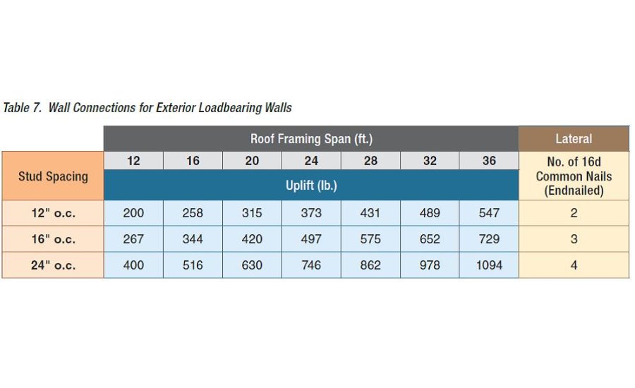
Figure 3. WFCM High Wind Guide - 160 MPH Exposure C: Table 7
Table 12
1st Story
8d common fasteners
3-inch edge/ 12-inch field spacing requires 83 percent of wall to have full height sheathing (19.9 feet)
Bottom plate-to-frame connection = 4-16d common nails per foot
Hold down capacity = 7,300 pounds
2nd Story
8d common fasteners
6-inch edge/ 12-inch field spacing requires 77 percent of wall have full height sheathing (18.5 feet)
Bottom plate-to-frame connection = 3-16d common nails-per-foot
Hold down capacity = 4,360 pounds
Combined 1st and 2nd story hold down requirement = 7,300 pounds + 4,360 pounds = 11,660 pounds
Maximum Building Dimension (L) – 32-foot dimension
Table 13
1st Story
8d common fasteners
4-inch edge/ 12-inch field spacing requires 66 percent of wall have full height sheathing (21.2 feet)
Bottom plate-to-frame connection = 3-16d common nails-per-foot
Hold down capacity = 5,900 pounds
2nd Story
8d common fasteners
6-inch edge/ 12-inch field spacing requires 53 percent of wall have full height sheathing (17.0 feet)
Bottom plate-to-frame connection = 3-16d common nails-per-foot
Hold down capacity = 4,360 pounds
Combined 1st and 2nd story hold down requirement = 5,900 pounds + 4,360 pounds = 10,260 pounds
Note that when full height segments meet at a corner, a single hold down shall be permitted to be used to resist the overturning forces in both directions when sized to resist the larger load and the corner framing in the adjoining walls is fastened together to transfer the uplift load. Therefore, a single 11,660 pounds hold down can be used at each corner.
")


